IMET - M550 ALL1-EN 19/53
5.5. Connection diagrams for L and K receivers
L and K receiving units are equipped with 1 slot that can be used for:
1 card with relay outputs for AC or DC versions or, alternatively
1 card with MOSFET outputs + 1 card with analog outputs for DC versions only
The safety controls and the basic functions are located directly on the motherboard, as shown in the
table in Chap. 5.3.
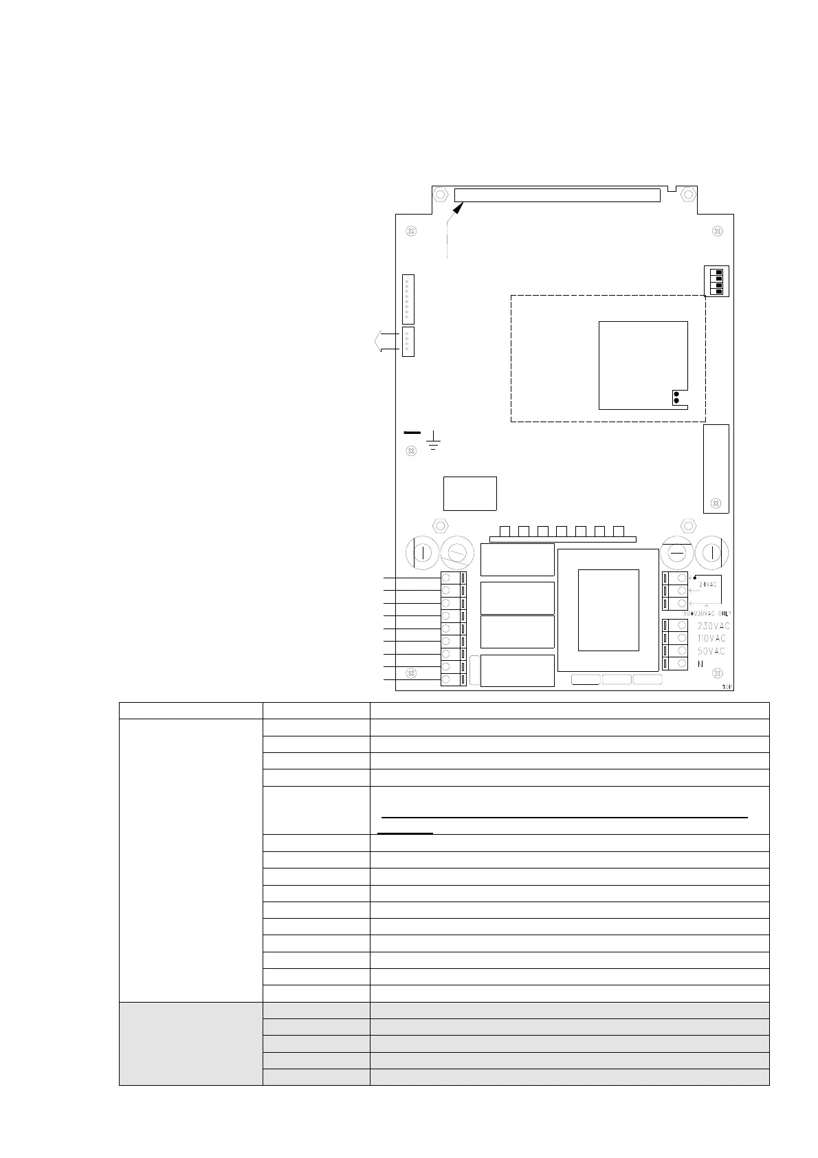
5.5.1. L-AC Version
Options on request SYMBOL DESCRIPTION
N
Neutral for main power supply 50/110/230V AC
50V AC
Input for 48-55V AC power supply
110V AC
Input for 110V AC power supply
230V AC
Input for 230V AC power supply
50-230V AC
ONLY
Connection for power supplies from 48V AC to 230V AC
MUST BE DISCONNECTED IN CASE OF 24V AC POWER
SUPPLY
24V AC
Input for 24V AC power supply
F13
T80mA L250V with 230V AC power supply
F13
T200mA L250V with 110V AC power supply
F13
T315mA L250V with 48-55V AC power supply
F10
T1.25A L250V power supply fuse
S-STOP
Safety-Stop relay connection
F11
T5A L250V S-STOP contact protection fuse
E- STOP
Emergency-Stop contact
F12
T5A L250V E-STOP contact protection fuse
START
NO/NC relay output
SERIAL
CONNECTION
CABLE
D0
DATA IN for RS232 serial
VIN=ENABLE
Input enabling RS232 (down active)
+10,7
10.7V DC Imax=250mA auxiliary voltage output
GND
Ground connection input
1
2
3
4
5
6
7
8
9
10
11
12
13
14
15
16
F11 F12
F13 F10
SAFETY
STOP
E-STOP A
E-STOP B
START
RF BUSY
POWER SUPPLY
WORKING
DATA ERROR CH. B
PASSIVE EMERGENCY CH. B
DATA ERROR CH. A
PASSIVE EMERGENCY CH. A
ON
START C
START NC
START NO
E-STOP B C
E-STOP A NO
E-STOP A C
SAFETY STOP C
SAFETY STOP NO
E-STOP B NO
SLOT PER INSERIMENTO SCHEDE
DIPSWITCH
EEPROM
CAVO SERIALE