IMET - M550 ALL1-EN 13/53
5.3. Basic functions
The table below shows the basic functions available on almost all receivers.
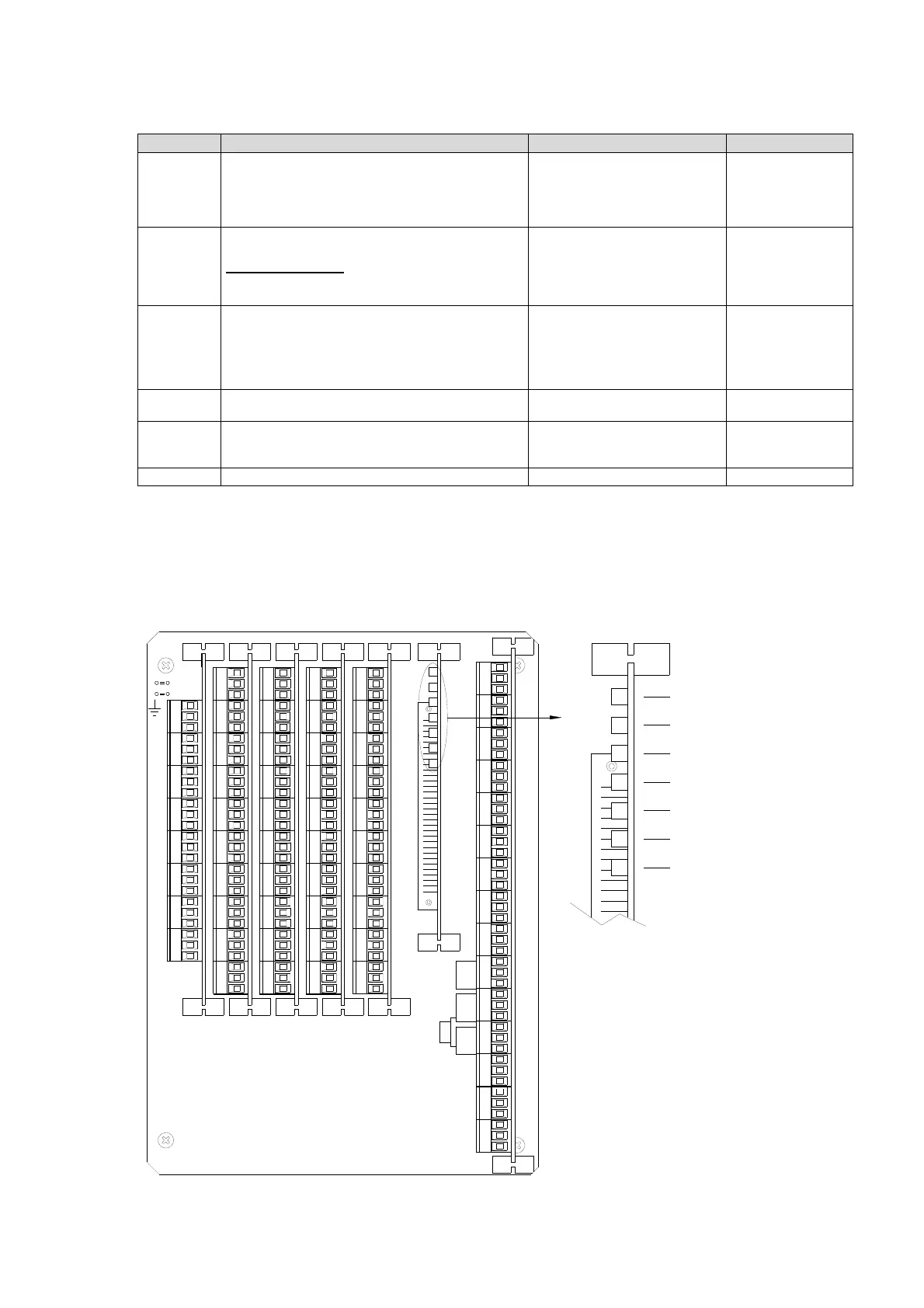
5.4. Connection diagrams of H receivers
Receiving unit version H is provided with 7 slots where the control relay cards, the analogue output
cards and the data feedback card are plugged in. Slot A includes, as well as the group A controls, the
basic functions in the table above.
NC
5
5
NC
NO NO
NC
C
NO
NO
NC
C
12
NO
NO
NC
C
NC
C
4
3
21
C
NO
NO
C
NC
NC
43
NO
NO
C
NC
NC
C
CC
NC
NO
NC
C
C
NO
6
7
NO
NC
NC
C
C
NO
89
NC
67
NO
C
NC
C
NO
89
NO
NC
C
NC
C
NO
SLOT E
NO
NC
C
10
10
NO
NC
C
NC
5
NC
5
2
3
41
NO
NO
NO
NC
NO
NC
NO
NC
NC
214
3
C
C
C
C
NO
NO
NO
C
NC
NC
C
NO
NO
C
NC
NC
C
C
LAMP
NO
NC
NO
NO
NC
NO
NC
NO
NO
NO
START HORN E-STOP E-STOP
C
C
C
C
C
NO
NO
NC
NO
NO
NC
NO
NC
S-STOP T-STOP
A2A1
C
C
C
C
LOGICA
+
RADIOSLOT C
106
7
89
C
NO
NC
NO
NC
NO
NC
NC
NO
6
7
89
C
C
C
C
NC
NO
10
SLOT D
C
C
NC
NO
C
NC
C
NO
NO
NC
C
NC
C
NO
SLOT B
NC
C
NO
SLOT A
A7
NC
NO
NO
NC
NO
NC
NO
NC
NC
A5
A4
A3
A6
C
C
C
C
NC
NO
A8
C
C
SLOT F
AD5AD6AD7AD8AD1 AD2 AD3 AD4
PASSIVE EMERGENCY CH. A
DATA ERROR CH. A
PASSIVE EMERGENCY CH. B
DATA ERROR CH. B
WORKING
POWER SUPPLY
RF BUSY
Relay Function Typical Uses Remarks
T-STOP The relay is activated for 5 seconds from the moment
the radio remote control is switched off or enters
passive emergency mode.
The T-STOP can be activated at switch-off or with a 2
second delay.
• Delayed STOP of
combustion engine
• Engine deceleration
S-STOP The relay is activated only by an instable command
from a toggle switch, button or joystick
Connected in series
, the function introduces a
redundancy that can be used to increase function
safety
• Enables the drain valve
• Common enabling of control
commands
Relays constantly
monitored by uP.
Opens with a 0.8
second delay
E-STOP The two relays are activated when the radio remote
control is switched on (STOP RELAY cat. 4 UNI
EN954-1 e PL e ISO13849-1) and stay active until a
STOP command intervenes (pressing the STOP
button or passive emergency)
• Powers the main contactor
in the machine’s control box
• Common power supply for
control commands
• Machine power supply
Relays constantly
monitored by uP
HORN Horn control relay Warns of potentially hazardous
situations
it can be associated
to the first START
START START control relay Powers the machine’s control box
and enables machine Start
function
LAMP Blinker control relay Blinker power supply
In its basic configuration the receiving unit
is supplied with a relay card (on slot A)
and a logic board.
Depending on project specifications, units
may include cards for control groups B, C,
D, E, an analog output card and, in case
of dual transmission, a data feedback
card
Note: On each project the controls are
based on a unique configuration that may
be changed only by IMET.