IMET - M550 ALL1-EN 25/53
5.7. Connection diagrams for M-AC receivers
M receivers are designed for industrial applications and come in 4 standard versions:
Version S: single transmission
Version D SPP: dual transmission with data acquisition via parallel port
Version D RS232: dual transmission with data acquisition via RS232 serial port
Version D RS485: dual transmission with data acquisition via RS485 serial port
The safety controls and the basic functions are located directly on the motherboard, as shown in the
table in Chap. 5.3.
Attention: with AC power supply it is MANDATORY to insert a transformer with double
isolation or with reinforced isolation, between the main power supply of the control box and
the receiver (available upon request)
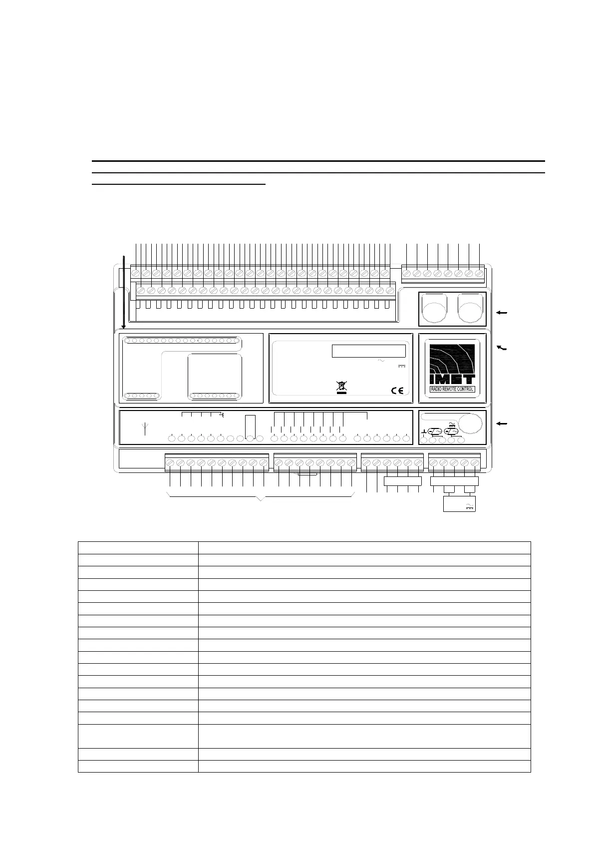
5.7.1. M-AC receiver
LB304
T 5A L250V T 5A L250V
T 1.25A L250V
13 - 24V
N L
7978777675
FUSE
E-STOP A S-STOP
FUSE
FUSE
SUPPLY
POWER
RF BUSY
C5
C4
C3
C2
C1
A8
A7
A6
A5
A4
A3
A2
A1
B8
B7
B6
B5
B4
B3
B2
B1
WORKING
DATA ERROR CH. B
EMERGENCY CH. B
POWER SUPPLY
EMERGENCY CH. A
DATA ERROR CH. A
LB306
IN RS232
ANT
LB534
+5VREF
AD IN 4
AD IN 3
AD IN 2
AD IN 1
AD GND
D7
D6
D5
D4
D3
D2
D1
D0
OUT VREF
DCOM
AD OUT 5
AD OUT 6
AD OUT 7
AD OUT 8
51 52 53 54 55 56 57 58 59 60 61 62 63 64 65 66 67 68 69 70
71 72
73
74
LB422
LB309
LB307
1,2A 20VA
13 - 24V 50/60HzSupply AC
Power
Serial no.
Supply DC 13 - 24V
M550S - UHF ISM BandRadio Model
RX Unit Mod. M550S MAC
START C
START NO
E-STOP B C
E-STOP B NO
E-STOP A C
E-STOP A NO
S-STOP NO
S-STOP C
GND
SUPPLY
POWER
13-24V
POWER IN
N.C.
ANALOG OUTPUT 8
ANALOG OUTPUT 7
ANALOG OUTPUT 6
ANALOG OUTPUT 5
N.C.
OUT VREF
ANALOG
OUTPUTS
C1 C
C1 NO
C1 NC
C2 C
C2 NO
C2 NC
C3 NO
C3 C
C4 NO
C4 C
C5 NO
C5 C
B1 C
B1 NO
B1 NC
B2 C
B2 NO
B2 NC
B3 NO
B3 C
B4 NO
B4 C
B5 NO
B5 C
B6 NO
B6 C
B7 NO
B7 C
B8 NO
B8 C
A1 NO
A1 C
A2 NO
A2 C
A3 NO
A3 C
A4 NO
A4 C
A5 NO
A5 C
A6 NO
A6 C
A7 NO
A7 C
A8 NO
A8 C
LAMP NO
LAMP C
HORN NO
HORN C
SYMBOL DESCRIPTION
START
NO relay output
E- STOP A
STOP relay connection
E- STOP B
STOP relay connection
S-STOP
Safety-Stop relay connection
E-STOP FUSE
T5A L250V E-STOP contact protection fuse
S-STOP FUSE
T5A L250V S-STOP contact protection fuse
HORN
Horn control output
LAMP
Blinker control output
A1….A8
NO relay control output
B1….B8
NO relay control output (outputs B1 and B2 with NO/NC contacts)
C1….C5
NO relay control output (outputs C1 and C2 with NO/NC contacts)
ANT
SMA connection for antenna cable
GND
Common line for input and output signals
POWER IN
Input for main power supply
POWER SUPPLY
FUSE
T1.25A L250V power supply fuse
ANALOG OUTPUT 5-8
Analog data outputs
OUT-VREF
10.7V DC Imax=250mA auxiliary voltage output