33
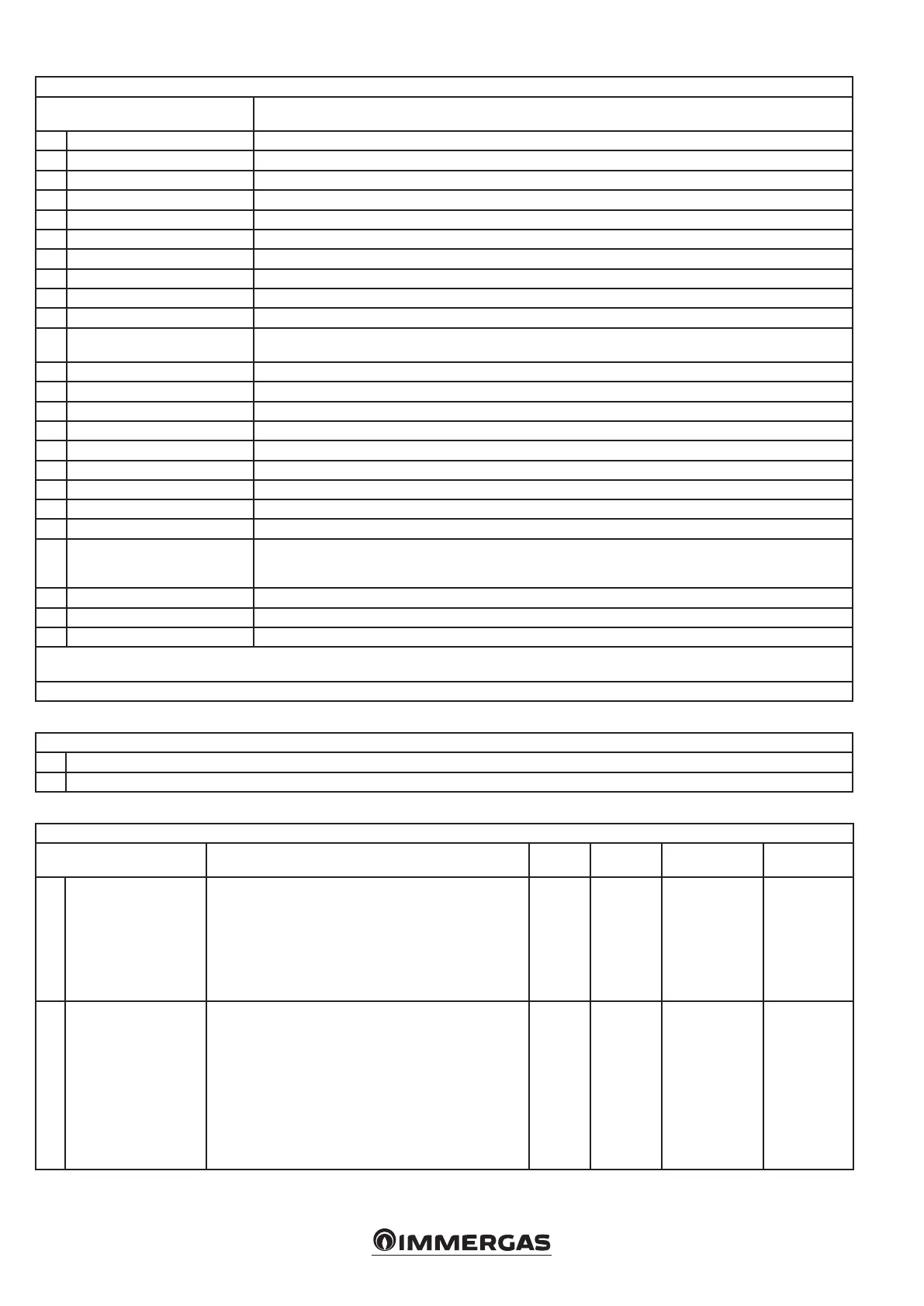
TECHNICIAN/Diagnostics/System Information menu
Menu item Description
1. Flame current * Value in µA.
2. Actual fan speed Real-time fan speed (rpm).
3. Required fan speed Fan setpoint (rom).
4. Modulation level * Eective burner output value (%).
5. Boiler setpoint * Temperature value calculated by the system (°C) **.
6. CH setpoint * Required temperature value during heating (°C) **.
7. DHW setpoint * Required temperature value in DHW phase (°C) **.
8. Boiler ow temperature * Temperature value measured by the system ow regulation probe (°C).
9. Return temperature * Temperature value measured by the system return control probe (°C).
10. Flue gas temperature * Temperature value measured by the ue probe (°C).
11. Flue temperature threshold
Error intervention threshold when the value detected by the ue probe is exceeded (high ue temperature limit)
(Error code 84).
12. External temperature * Temperature value measured by the external probe (°C) **.
13. Boiler temperatures * Temperature value measured by the DHW probe (°C) **.
14. System temperature * Temperature value measured by the system-side ow probe (°C) **.
15. Mixed zone temperature * Temperature value measured by the low temperature ow probe (°C) **.
16. Mixed zone setpoint Required temperature value for the low-temperature zone (°C) **.
17. Water pressure * Pressure value measured by the pressure transducer (bar).
18. Pump speed Real-time pump speed (%).
19. Pump feedback Pump status (%).
20. Number of burners Number of appliances installed (1 = single boiler) **.
21. Cascade role
Role of the appliance in the simple cascade (Master if single appliance or if simple cascade Master appliance, Slave if
simple cascade Slave appliance followed by the number assigned during cascade conguration).
22. Number of burners ON Number of burners on **.
23. Cascade modulation level Eective power value of the simple cascade (%) **.
24. Input 0/10V Voltage value at the 0-10V input.
* When a line has a “*” at the end, pressing OK when the line is highlighted will open a graph showing the last 120 variable values stored every 12 minutes (24-
hour history). e sample will not be averaged over the 12-minute period.
** Valid only for Master and single appliance.
TECHNICIAN/Cascade Menu
1. Single burner power
2. Autodetect
TECHNICIAN/Cascade/Single burner power menu
Menu item Description Range Default Synchronisation
Customised
value
1. Maximum
Denes the maximum eective power of the individual ap-
pliance. is parameter is used within the control algorithm.
If the maximum power is changed via the 'Maximum power'
parameters (DHW and heating), this parameter should not
be adjusted, as depowering acts at the cascade level and not
at the individual appliance level. If the maximum fan speed is
changed, this parameter must be adjusted to the new maxi-
mum power obtained.
0 - 255
(kW)
Factory
preset
(See boiler
booklet)
No
2.
Minimum modulation
level
Denes the actual modulation ratio of the individual appli-
ance. is parameter is used within the control algorithm. If
the maximum power is changed via the "Minimum power"
parameters (DHW and heating), this parameter should not be
adjusted, as the change in power acts at the cascade level and
not at the individual appliance level. If the minimum fan speed
is increased, it may be necessary to adjust this parameter.
Note: with collective ue system use, the minimum fan speed
is increased to bring the individual appliances to the mini-
mum ow rate as per the data sheet; in this case this parameter
should not be adjusted.
0 - 100
(%)
Factory
preset
(See boiler
booklet)
No






 To Next Page