38
INSTALLERUSERMAINTENANCE TECHNICIANTECHNICAL DATA
1.17 OUTDOOR INSTALLATION IN PARTIALLY PROTECTED AREA
is appliance can be installed outdoors in a partially protected area (except when integrated in the Trio Pack Hybrid).
By partially protected area, we mean one in which the unit is not directly exposed to the elements (rain, snow, hail, etc.).
If the appliance is installed in a location where the ambient temperature falls below -5°C, use the optional antifreeze kit, check-
ing the ambient temperature range for operation in the technical data table in this instruction manual (Section 'Technical
Data').
is type of installation is possible when permitted by the laws in force in the appliance's country of destination.
Conguration type B, open chamber and fan assisted (B
23
or B
53
).
Using the relevant cover kit, direct air intake is possible and ue gas is exhausted into a single ue or directly to the outside. In this cong-
uration it is possible to install the appliance in a partially protected place. In this conguration the appliance is classied as type B.
With this conguration:
- air intake takes place directly from the environment in which the appliance is installed (external);
- the ue gas exhaust must be connected to its own single chimney (B
23
) or ducted directly outside via a vertical terminal for direct ex-
haust (B
53
) or via an Immergas ducting system (B
53
).
e technical regulations in force must be respected.
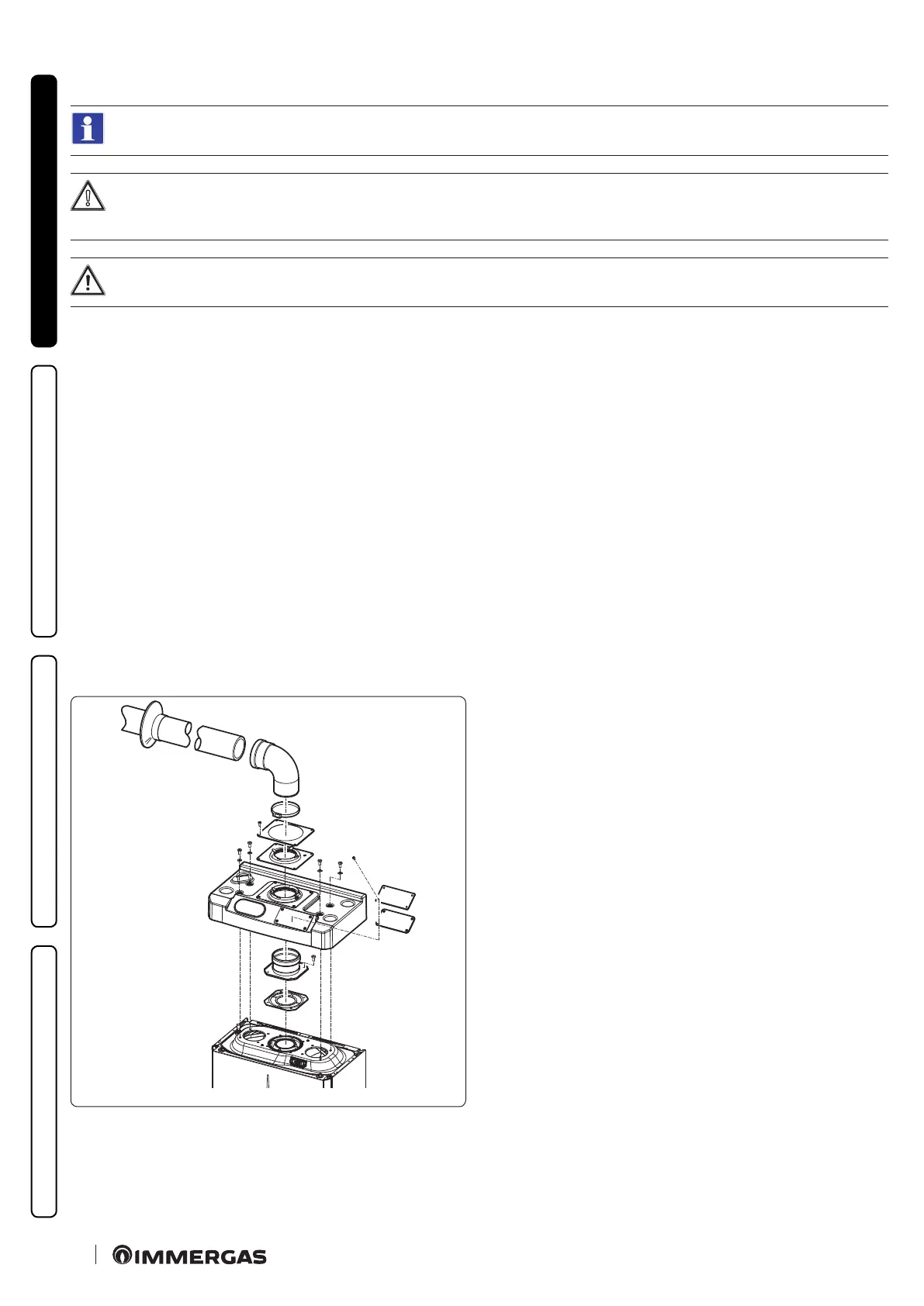
Cover kit assembly (Fig.15).
Remove the two plugs from the two lateral intake holes.
Install the Ø 80 outlet ange on the central hole of the boiler, taking care to insert the gasket supplied with the kit and tighten by means of
the screws provided.
Install the upper cover, xing it using the 4 screws present in the kit, positioning the relevant gaskets.
Engage the 90° Ø 80 bend with the male end (smooth) in the female end (with lip seal) of the Ø 80 ange unit to the end stop. Introduce the
gasket, making it run along the bend. Fix it using the metal sheet plate and tighten by means of the clips present in the kit, making sure to
block the 4 gasket aps.
Fit the male end (smooth) of the exhaust pipe into the female end of the 90° Ø 80 bend, making sure that the relevant wall sealing plate is
already tted; this will ensure hold and joining of the elements making up the kit.
15
e cover kit includes (Fig. 15):
N°1 ermoformed cover
N°1 Gasket clamping plate
N°1 Gasket
N°1 Gasket tightening clip
e terminal kit includes (Fig. 15):
N°1 Gasket
N°1 Exhaust ange Ø 80
N°1 Ø 80 90° bend
N°1 Exhaust pipe Ø 80
N°1 Wall sealing plate