87
INSTALLER
USERMAINTENANCE TECHNICIAN
TECHNICAL DATA
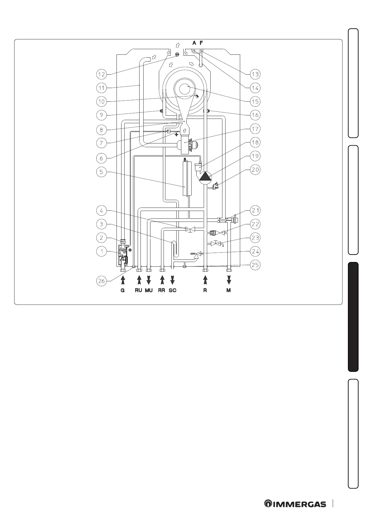
3.4 HYDRAULIC DIAGRAM
53
Key (Fig. 53):
1 - Gas valve
2 - Gas nozzle
3 - Condensate drain trap
4 - Filling valve / tap
5 - System expansion vessel
6 - Positive (+) pressure point
7 - Pressure signal vent tting
8 - Venturi
9 - Flow probe
10 - Ignition / detection electrode
11 - Air intake pipe
12 - Flue probe
13 - Flue sample point
14 - Air sample point
15 - Burner
16 - Return probe
17 - Fan
18 - Air vent valve
19 - Pump
20 - Absolute pressure switch
21 - 3-way valve (motorised)
22 - By-pass
23 - System draining valve
24 - 3 bar safety valve
25 - 3 bar safety valve drain tting signal
26 - Air vent valve drain
G - Gas supply
RU - Storage tank unit return
MU - Storage tank unit ow
RR - System lling
SC - Condensate drain
R - System return
M - System ow