88
INSTALLER
USERMAINTENANCE TECHNICIAN
TECHNICAL DATA
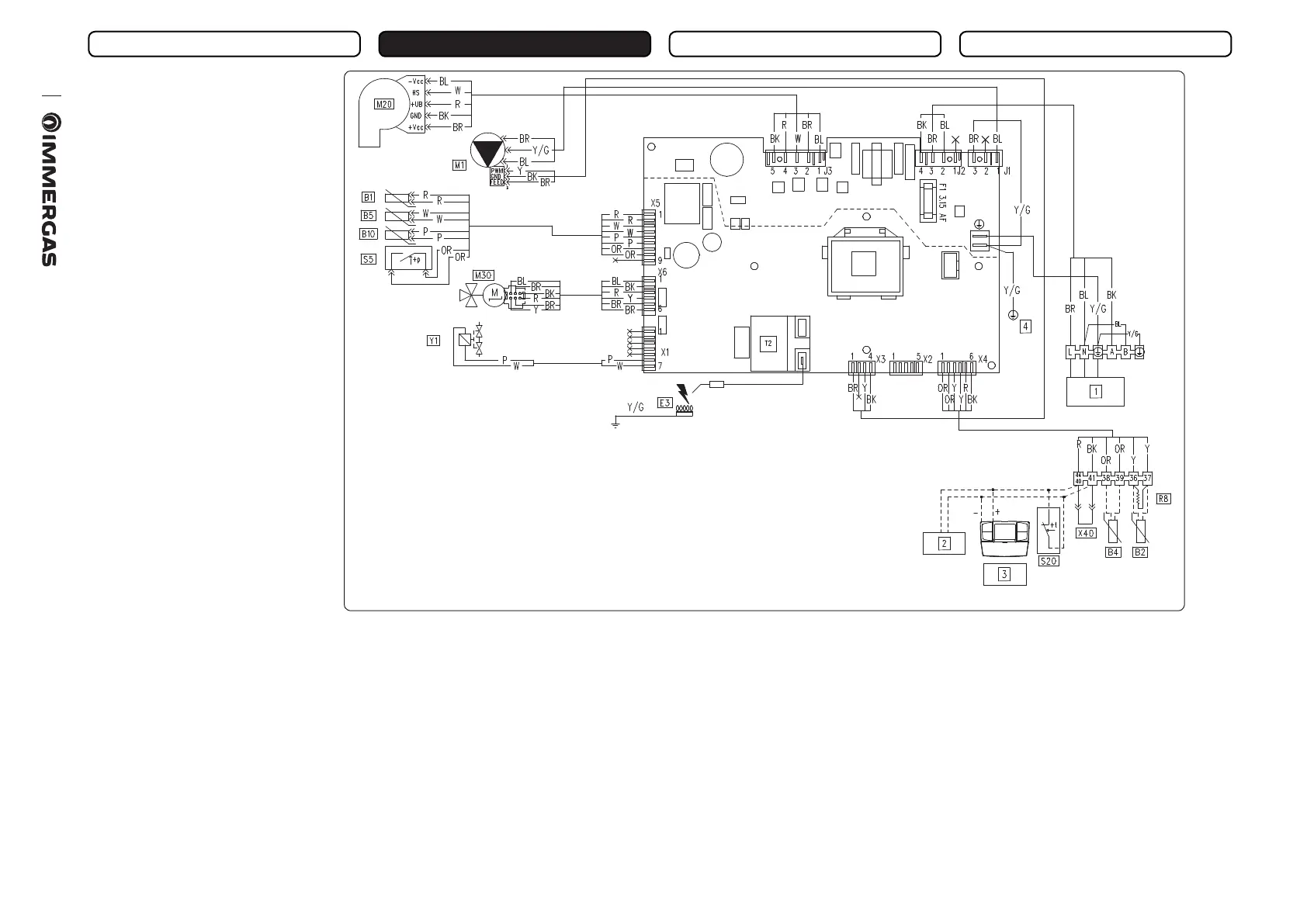
Key (Fig. 54):
B1 - Flow probe
B2 - Boiler probe (optional)
B4 - External probe (optional)
B5 - Return probe
B10 - Flue probe
CAR
V2
- Comando Amico Remoto
V2
re-
mote control (optional)
E3 - Ignition and detection elec-
trode
M1 - Boiler circulating pump
M20 - Fan
M30 - ree-way stepper motor
R8 - Stor.tank function resistance
function
S5 - System pressure switch
S20 - Room thermostat (optional)
T2 - Ignition transformer
X40 - Room thermostat link
Y1 - Gas valve
Colour code key (Fig. 54):
BK - Black
BL - Blue
BR - Brown
G - Green
GY - Grey
OR - Orange
P - Purple
PK - Pink
R - Red
W - White
Y - Yellow
Y/G - Yellow/Green
1 - 230 Vac - 50Hz Power supply
2 - IMG BUS (optional)
3 - CARV
2
(optional)
4 - Earth - Frame
54
Comando Amico Remoto
V2
: the boiler is prepared for the application of the Comando Amico Remoto remote control
V2
(CA R
V2
), which must
be connected to clamps 41 and 44/40 of the terminal board (located in the boiler control panel) respecting the polarity and eliminating link
X40.
Room thermostat: the boiler is prepared for the application of the room thermostat (S20), which must be connected to clamps 44/40 - 41 of the
terminal board (located in the boiler control panel) eliminating link X40.
Storage tank unit: the boiler is prepared for connection to a storage tank unit, which must be connected to terminals 36 and 37 of the terminal
board (placed inside the connections compartment), eliminating resistance R8.
3.5 WIRING DIAGRAM
 Loading...


