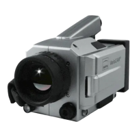
User Manual for the Thermographic System VarioCAM
®
high resolution
3. Technical Description
6 © InfraTec GmbH 2013 User Manual
Thermographic system of resolution (384 x 288) pixels
lens focal length (mm) min. focus (m) IFOV (mrad) FOV (°)
wide-angle lens 12.5 0.2 2.8 (57 x 44)
standard lens 25 0.3 1.4 (30 x 23)
telephoto lens 1 50 2.0 0.7 (15 x 12)
telephoto lens 2 75 2.0 0.47 (10 x 8)
telephoto lens 3 130 5.0 0.27 (6 x 4)
close-up lens focal length (mm) focus (mm) field of view (mm²) resolution (μm)
close-up 0.17x for 25 149 (80 x 60) 209
close-up 0.5x for 25 50 (27 x 20) 70
microscopic lens 1.0x - 50 (13 x 10) 35
Thermographic system of resolution (640 x 480) pixels
lens focal length (mm) min. focus (m) IFOV (mrad) FOV (°)
wide-angle lens 12.5 0,2 2.0 (65 x 51)
standard lens 30 0,3 0.8 (30 x 23)
telephoto lens 1 50 2,0 0.5 (18 x 14)
telephoto lens 2 75 2,0 0.3 (12 x 9)
telephoto lens 3 130 5,0 0.2 (7 x 5)
close-up lens focal length (mm) focus (mm) field of view (mm²) resolution (μm)
close-up 0.17x for 30 150 (80 x 60) 125
close-up 0.5x for 30 50 (27 x 20) 42
microscopic lens 1.0x - 50 (16 x 12) 25
Detector
The VarioCAM
®
hr has an uncooled microbolometer FPA detector (uncooled Focal Plane Array). The
detector is thermally stabilised with high precision using a Peltier element and is thus independent of the
ambient temperature.
The various elements of the detector are microscopically minute thin-film resistors on wafer-thin
membranes, which are arranged cantilevered a few micrometers above the silicon read-out circuit. The
thermal radiation of the scene is imaged by the lens of the thermographic system on these detector
elements and absorbed by them. The temperature change of the detector elements resulting therefrom
yields electronically evaluable signals which can be read out line-wise and column-wise by a read-out
circuit.
Applying an uncooled detector guarantees quick availability of the camera function after switching it on
(start-up time < 60 seconds) and long service life (MTTF) in permanent use.
Detector electronics
The detector electronics supplies the BIAS voltages required for detector operation and further control
signals, and it takes care of the pre-processing and digitalisation of the analog video output signal from
the detector.