User Manual for the Thermographic System VarioCAM
®
high resolution
7. Starting up
User Manual © InfraTec GmbH 2013 21
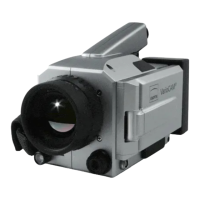
Connection Breakout Box – Option 2
Fig. 27 Trigger Cable Breakout-Box -
Option 2
Power supply, 12 V DV supply voltage
Connection for system cable to the
VarioCAM
®
hr
Trigger input/trigger output
Fig. 27 Breakout Box – option 2 (power supply, camera connection, Trigger)
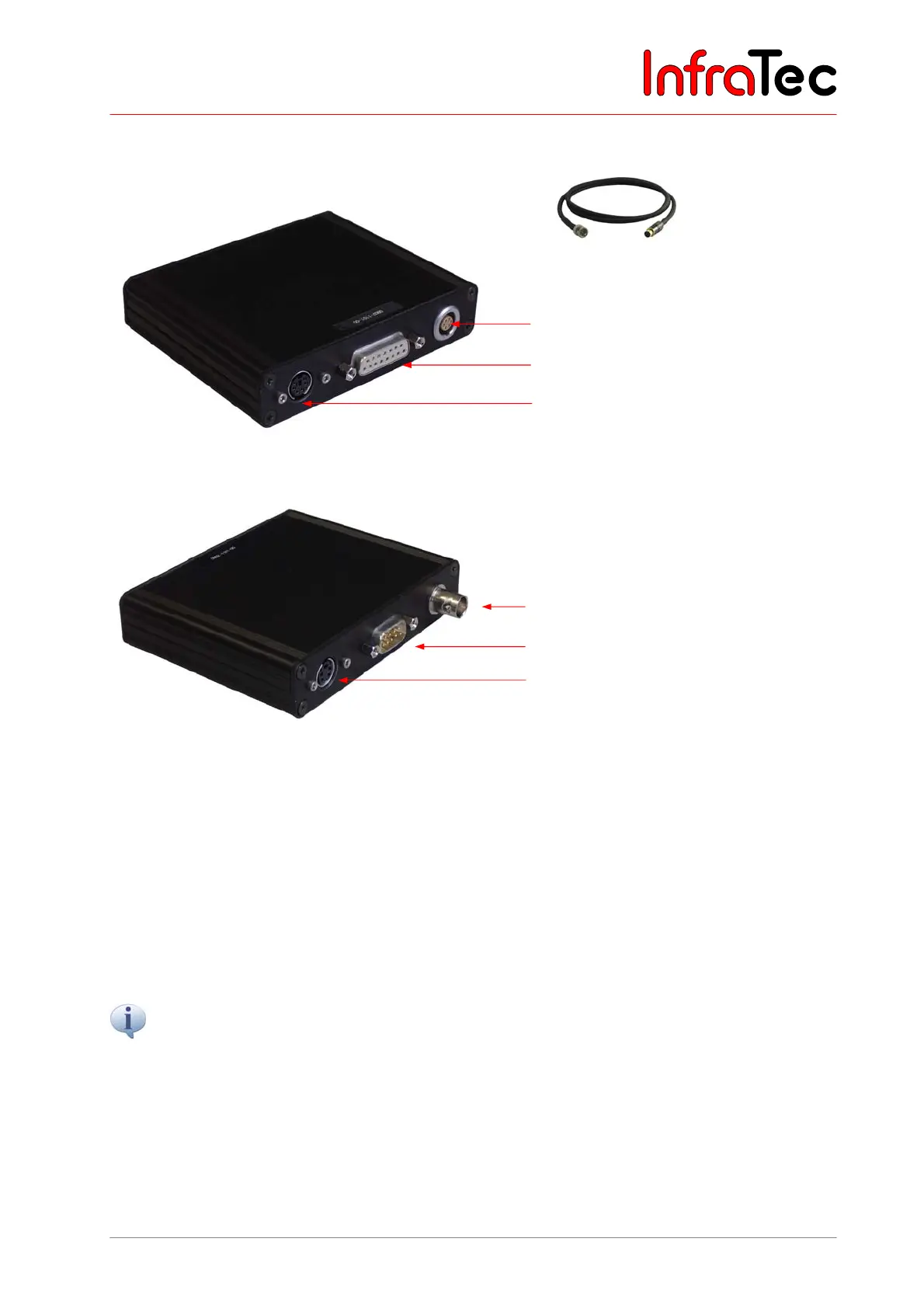
Fig. 28 Breakout Box – option 2 (BNC, RS232, S-Video)
7.9 Trigger Functionality VarioCAM
®
high resolution
Triggering only affects the 16-bit data transmission via FireWire. A 14-core system cable transmits the
TTL/CMOS-signal from the interfaces “T1” and “T2” on the Breakout Box to the VarioCAM
®
hr. Use the
included trigger cables in order to connect the Breakout Box, see Fig. 24 and Fig. 27.
■ T1 Trigger channel 1 is used by software IRBIS
®
3.
■ T2 Trigger channel 2 is reserved for SDK and further specific applications.
The voltage level of the VarioCAM
®
hr’s input and output is 5 V TTL/CMOS.
The VarioCAM
®
hr reacts to low-high trigger edges. The trigger event effects a tagging of the FireWire
header index of the next frame (IR image). This tag will be evaluated by the IRBIS
®
3-implemented
IRBGRAB.DLL, which will then save the respective data. The minimum length of the trigger signal is 10
ns. However, the impulse should not be shorter than approximately 3 ms in order to make for a precise
assignment to the current frame. Nevertheless, a cadence with a duty cycle of 1:1 is also possible.
BNC video connection (PAL/NTSC-FBAS)
Serial interface (RS232)
S-Video