User Manual for the Thermographic System VarioCAM
®
high resolution
7. Starting up
20 © InfraTec GmbH 2013 User Manual
7.8 Operation with Breakout Box (Connection via RS232)*
The use of the Breakout Box extends the options of connection of the VarioCAM
®
hr. The analog outputs
PAL/NTSC-FBAS and S Video as well as the digital RS232 interface are accessible via the Breakout Box.
Please follow the instructions as provided for making the desired connection.
1. At first, connect the thermographic camera and Breakout Box. For this purpose use the included 14-
pine system cable which is to be connected to the 14-pin (left) LEMO socket at the rear of the
thermographic system.
2. Then connect the Breakout Box to the COM interface of the host PC.
3. Now the included power supply unit is connected to the Breakout Box.
4. Only now you can press the C button at the rear of the camera to start the thermographic system.
Connection Breakout Box – Option 1
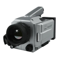
Fig. 24 Trigger Cable Breakout-Box –
option 1
S-Video
Connection for system cable to the
VarioCAM
®
hr
Power supply, 12 V DC supply voltage
Fig. 25 Breakout Box (S-Video, camera connection, power supply)
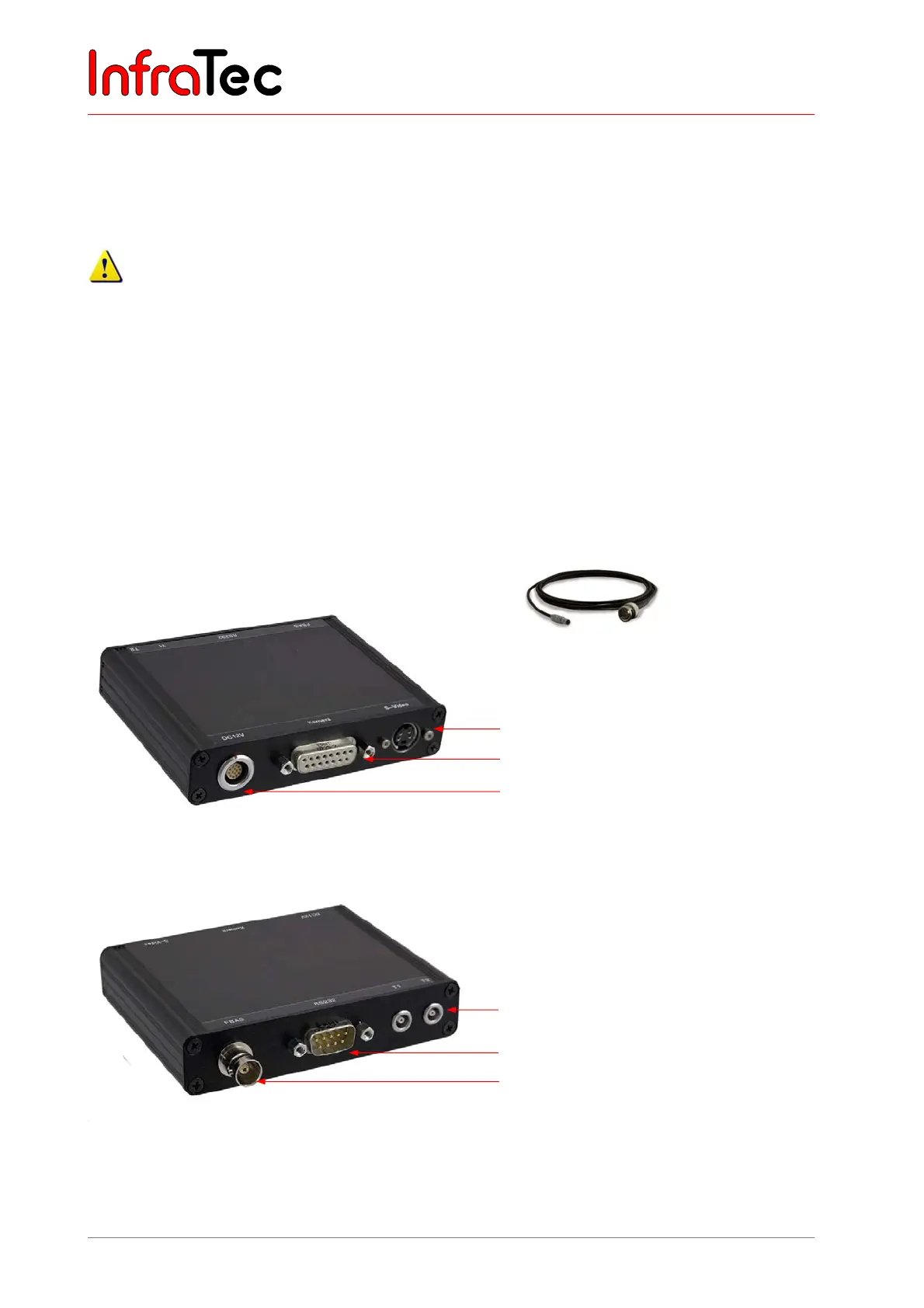
Fig. 26 Breakout Box (Trigger; RS232, BNC)
BNC video connection (PAL/NTSC-FBAS)
Serial interface (RS232)
Trigger T1, T2 (configurable)