User Manual for the Thermographic System VarioCAM
®
high resolution
10. Operating Software IRBIS® remote 3.0*
76 © InfraTec GmbH 2013 User Manual
When starting the programme, IRBIS
®
remote will check the connection to the thermographic system
VarioCAM
®
hr. Should no connection be possible via the FireWire interface of the computer to the
infrared camera, the programme will be trying, in a second step, to set up communication via the serial
interface.
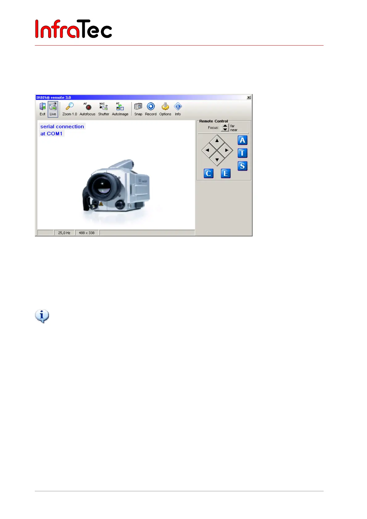
Fig. 161 IRBIS
®
remote – serial RS232 connection – as it appears on the screen
In the case of connection via the serial RS232 interface (Breakout Box* - see 7.8 Operation with Breakout
Box (Connection via RS232)* – page 20, only the keyboard commands will be transferred to the
thermographic system. The video image can be visualised via video interfaces “S-Video”, “VGA” or
“PAL/NTSC-FBAS” by means of a suitable replay device.
IRBIS
®
remote can only be used if the VarioCAM
®
hr has been started and connected with the control PC.
10.2 User Interface
Depending on the activated components, the user interface menu will vary. The menu (see Fig. 160, page
75) is subdivided into three principal areas:
■ Analog video display
■ Menu bar with quick keys
■ Controls for direct control
10.2.1 Analog Video Display
The area analog video display shows the video image as provided by the VarioCAM
®
hr. Interactive
processing of the imaged elements within the display screen is not provided for and is not supported by
the IRBIS
®
remote programme.
The size of the displayed image can be changed in fixed increments via the button “Zoom” (within the
menu bar).