User Manual for the Thermographic System VarioCAM
®
high resolution
7. Starting up
18 © InfraTec GmbH 2013 User Manual
7.7 Operation via the FireWire (IEEE 1394) Interface*
By means of the following connecting options, the VarioCAM
®
hr can be connected to the PC/notebook.
The accessories described are optionally included in the scope pf delivery*.
Please follow the instructions, i.e. always plug the FireWire cable into the computer first and then
connect it to the camera!
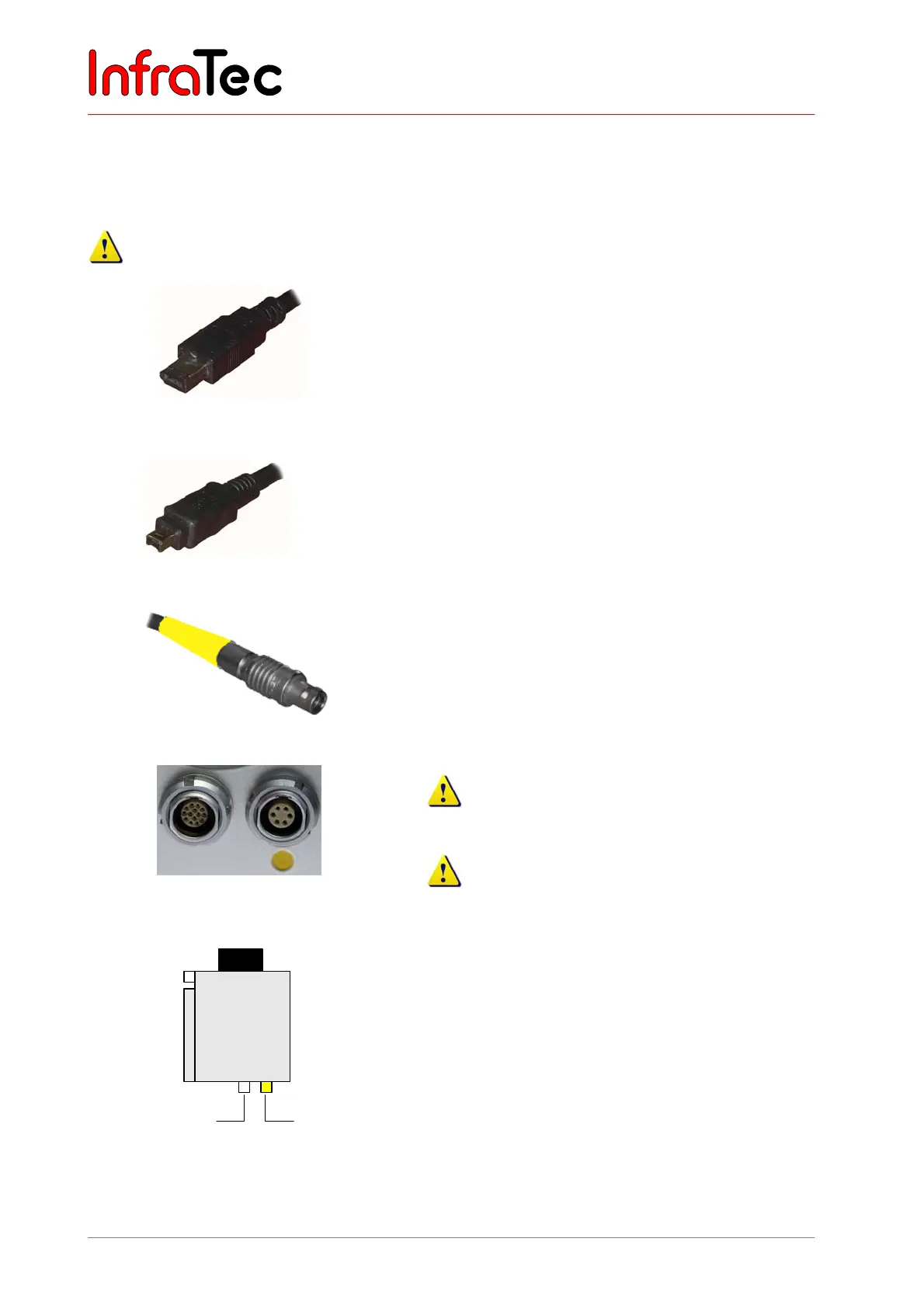
1) The 6-pin FireWire cable is used for making a
connection to the FireWire interface of the PC.
Fig. 16 FireWire (IEEE 1394) cable, 6-pin
1a) The 4-pin FireWire cable* is used for making the
connection to a notebook.
For this purpose, the 4-pin FireWire plug must be
connected to the FireWire output integrated in the
notebook (optionally a CardBus-FireWire card can
be used).
Fig. 17 FireWire (IEEE 1394) cable, 4-pin
2) The 6-pin LEMO plug (marked yellow) is connected
to the 6-pin LEMO socket (Fig. 19, marked yellow)
on the camera.
Fig. 18 LEMO plug, 6-pin
Fig. 19 LEMO socket, (14-pin left / 6-pin
right)
Please take care to connect to the correct LEMO
socket!
Plug the LEMO plug with the red dot showing on
the upside into the socket. Do not use any force!
VarioCAM®
hr
Power supply unit
14 6
LEMO
FireWire
Fig. 20 VC hr withFireWire cable and power
supply unit
VarioCAM
®
hr with FireWire cable and power
supply unit
The thermographic camera is connected via the
FireWire cable with the 6-pin LEMO socket (right,
marked yellow). The power supply unit power supply
unit is connected on the left to the 14-pin LEMO socket.