User Manual for the Thermographic System VarioCAM
®
high resolution
7. Starting up
User Manual © InfraTec GmbH 2013 19
When connecting the thermographic camera with the PC/notebook for the first time, automatic hardware
recognition will be activated. Further steps for installing the FireWire (IEEE1394) driver for the VarioCAM
®
hr
are described in Chapter 9.3, Installation of the FireWire Driver for the VarioCAM
®
hr, page 68.
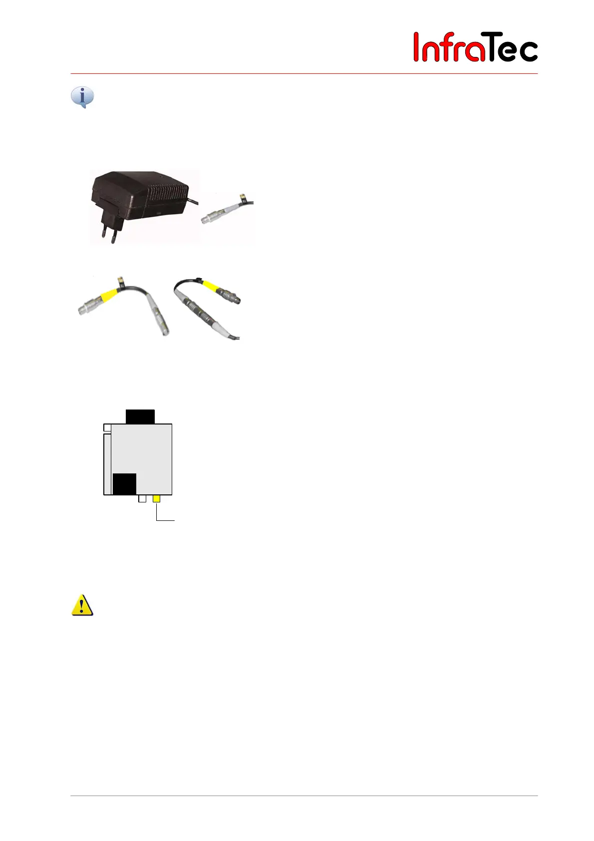
Connection with a power supply unit*
Fig. 21 Power supply unit with plug
When operating the VarioCAM
hr on a notebook
(FireWire connection without any power supply), the
thermographic system is to be connected via a power
supply unit by means of the 14-pin LEMO plug.
Fig. 22 LEMO adapter
As an alternative, power can also be supplied via the 6-
pin LEMO socket on the right at the rear of the
VarioCAM
®
hr or of the Breakout Box. For this purpose,
the LEMO adapter is connected to the power supply unit.
Connection without a power supply unit
VarioCAM®
hr
FireWire
614
LEMO
Battery
Fig. 23 VC hr with FireWire cable (and
battery)
VC hr with FireWire cable (and battery)
The VarioCAM
®
hr is connected via the FireWire cable
with the 6-pin LEMO socket on the right (each marked
yellow). The VarioCAM
®
hr is supplied with power via the
battery or the FireWire cable. An external power supply
unit is not required in this case.
Should the thermographic system VarioCAM
®
hr be operated on a PC without any power supply unit
(power supply via the FireWire interface), make sure that the FireWire cards recommended by
InfraTec are used. Otherwise InfraTec will not grant any functional guaranty.