User Manual for the Thermographic System VarioCAM
®
high resolution
7. Starting up
22 © InfraTec GmbH 2013 User Manual
VarioCAM®
hr
power
supply
unit
RS232 /
PAL/NTSC-FBAS /
S-Video
14
LEMO
Adapter P
6
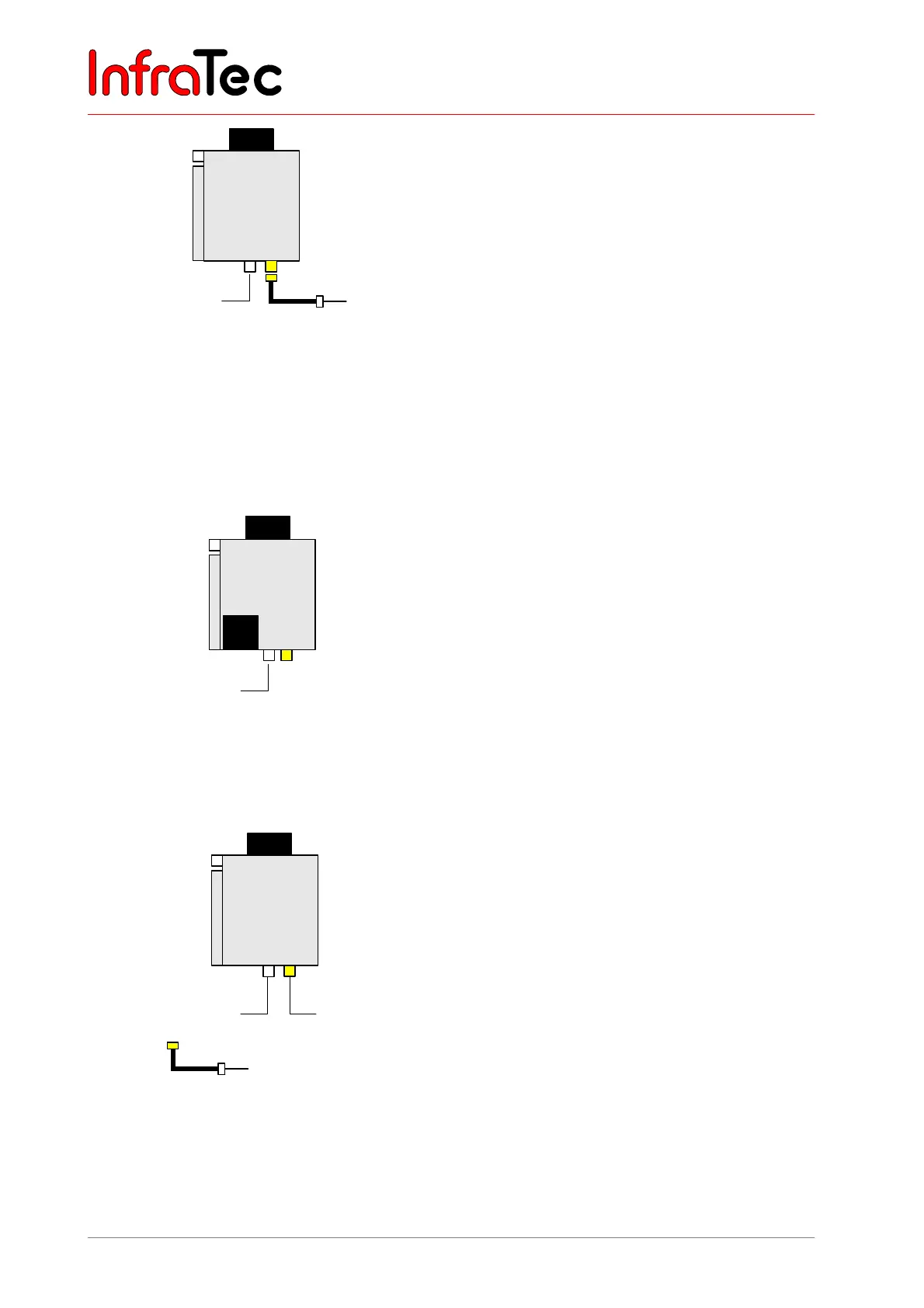
Fig. 29 VC hr with power supply unit and
universal cable or Breakout Box
(system cable)
VC hr with power supply unit and universal
cable or Breakout Box (with system cable)
The universal cable/system cable is connected to the 14-
pin LEMO socket on the left.
Using the universal cable RS232, the FBAS and S-Video
are accessible via appropriate standard connector
assemblies. The Breakout Box to be connected to the
system cable additionally has a trigger channel and DC-
IN.
VarioCAM
®
hr is supplied with power via the power
supply unit. For that purpose the 14-pin LEMO connector
of the power supply is connected to the 6- pin on the
right of the LEMO socket of the VarioCAM
®
hr via
adapter P.
Adapter P (power supply adapter) is only to be used
in connection with the power supply!
VarioCAM®
hr
614
RS232 /
PAL/NTSC-FBAS /
S-Video
LEMO
Battery
Fig. 30 VC hr with battery and universal
cable or Breakout Box (system
cable)
VC hr with battery and universal cable or
Breakout Box (with system cable)
The VarioCAM
®
hr is supplied with power via a
rechargeable battery. An external power supply unit is
not required in this case. The universal cable/system
cable is connected to the 14-pin LEMO socket of the
VarioCAM
®
hr.
VarioCAM®
hr
Power supply unit
RS232 /
PAL/NTSC-FBAS /
S-Video / Trigger
14
LEMO
Adapter P
6
FireWire
Fig. 31 VC hr with power supply unit,
universal cable or Breakout Box
(system cable)
VC hr with power supply unit, Breakout Box
(with system cable) and FireWire
The Breakout Box is connected to the 14-pin LEMO
socket of the VarioCAM
®
hr via the system cable. The
VarioCAM
®
hr is supplied with power via the power
supply unit. For that purpose the 14-pin LEMO plug of
the power supply is connected to the 6- pin LEMO socket
of the Breakout Box via Adapter P. FireWire can be
connected to the 6-pin LEMO socket on the right of the
VarioCAM
®
hr.
Please note that the 6-pin LEMO socket of the
Breakout Box exclusively serves the power supply
and that it does not permit connection of the
FireWire cable!