F3-03
V/F frequency F1 Factory default value 0.00Hz
Setup range 0.00Hz ~ rated motor frequency
F3-04
V/F voltage V1 Factory default value 0.0%
Setup range 0.0%~ 100.0%
F3-05
V/F frequency F2 Factory default value 0.00Hz
Setup range V1 ~ rated motor frequency
F3-06
V/F voltage V2 Factory default value 0.0%
Setup range F1 ~ 100.0%
F3-07
V/F frequency F3 Factory default value 0.00Hz
Setup range V2 ~ rated motor frequency
F3-08
V/F voltage V3 Factory default value 0.0%
Setup range F2 ~ 100.0%
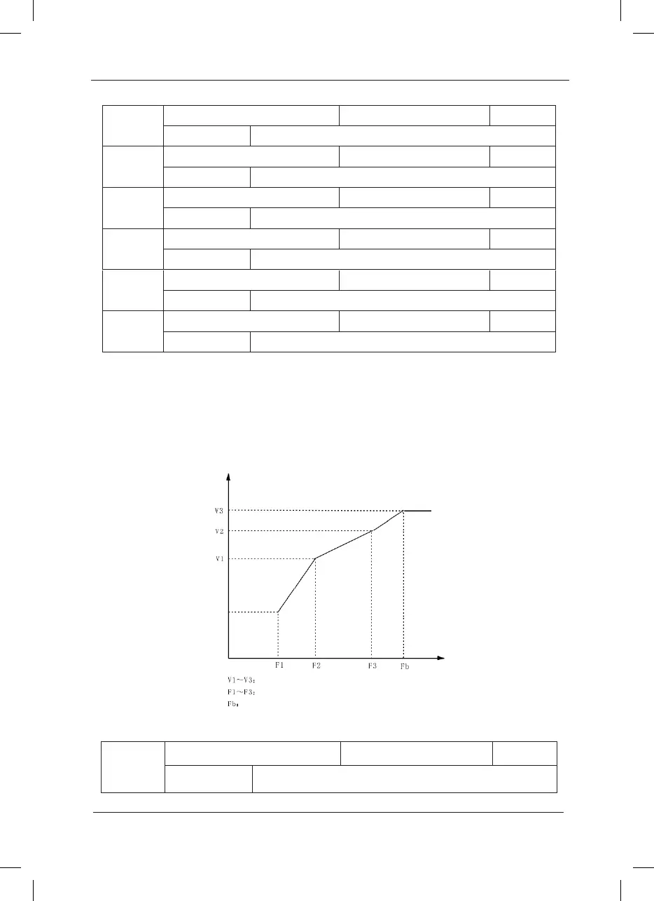
Six parameters of F3-03 to F3-08 dene MS V/F curve.
The setup value of V/F curve is generally set in accordance with the load characteristics of the
motor.
Caution: V1<V2<V3 and F1<F2<F3. In case of low frequency, higher setup voltage may cause
over heat and even burning of the motor and stall over current or current protection of the
inverter.
Voltage %
Frequency Hz
Segments 1 to 3 Voltage Proportion of MS V/F
Se gme nts 1 to 3 Freque ncy P oint of MS V/F
Rate d Motor Frequency F1=04
F3-09
Slip compensation coefcient Factory default value 0.0%
Setup range 0% ~ 200.0%
Fig.6-4 Schematic Diagram for V/F Curve Setup
 Loading...
