MD320/MD320N User Manual Appendix
187
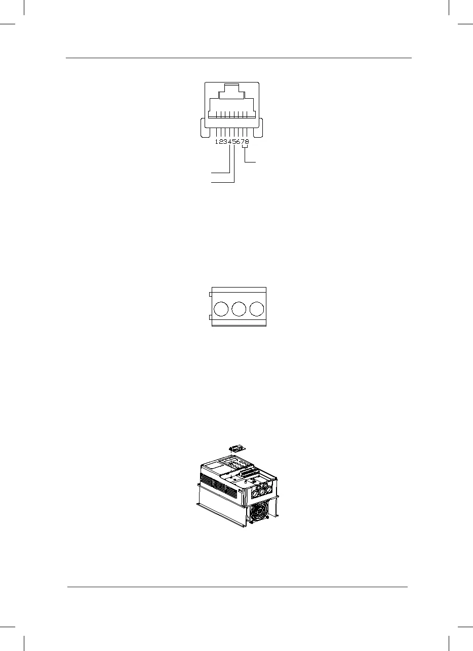
Appendix D: Fig.2 RS-232 Signal Denition
Description of RS-485 communication card: The physical structure and connecting mode
are as shown in the following figure. RS-485 communication mode provides two types of
connections, which are mutually connected. The user can freely select the communication line
connections based on the actual needs. The physical structure and connecting mode are as
shown in Appendix D: Fig.1 Physical Structure and Connecting Mode, while the interface signal
definitions of the two connecting modes are as shown in Appendix D: Fig.3 RS-485 Signal
Denition.
Appendix D: Fig.3 RS-485 Signal Denition
D.1.3 Installation Mode
1) Installation shall be conducted when the inverter is completely disconnected from
power supply.
2) Align the communication card with the expansion card interface of the control board
of the inverter.
3) Tighten the communication card with screws, as shown in Appendix D: Fig.4
Installation Mode with Tightening Screws.
Appendix D: Fig.4 Installation Mode with Tightening Screws
D.1.4 Precautions
1) In order to avoid external interferences on the communication signal, it is recommended that
 Loading...
