can be determined by multiplying its binary number with 2. “1” on the toggle switch is the
binary lower bit, while “5” is the higher bit. When the toggle switch is switched to ON, the bit is
enabled and indicates “1” .Otherwise, it indicates “0”. The frequency division coefcient is as
shown in the table below:
Appendix A: Table 3 Terminal and Toggle Description
Binary number
Frequency division
coefcient
0 00000 no output
1 00001 no output
2 00010 2*2
… … …
i … i*2
31 11111 31*2
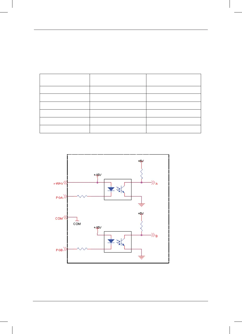
A.2.3 Principle Schematic Diagram
1. Schematic Diagram for Encoder Interface
 Loading...
