Mechanical and Electric Installation MD320/MD320N User Manual
58
This is one of the most commonly used connection mode. If external power supply is used, it
must remove the short circuit copper bars between +24V and OP and between COM and CME
respectively, and connect the positive pole of external power supply to OP and negative pole to
CME.
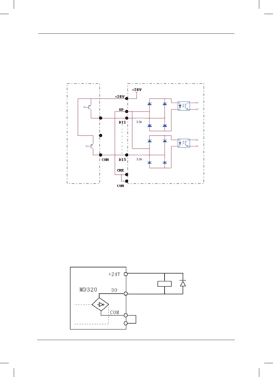
4. Drain Electrode Connection
Fig.3-14.Drain Connection
In this connection mode, it must remove the short circuit copper bar between +24V and OP and
connect OP with the public tend of the external controller and OP with CME. If external power
supply is used, it must also remove the short circuit copper bar between CME and COM.
D. Digital output terminal:
When the digital output terminal needs the drive relay, absorption diode shall be installed at the
two sides of the relay coil. Otherwise it may damage DC 24 power supply easily.
Caution: The absorption diode shall be installed with correct polarity, as shown in Fig.3-15.
Otherwise, when there the digital output terminal has output, the DC 24V power supply and
output circuit will be damaged immediately.
 Loading...
