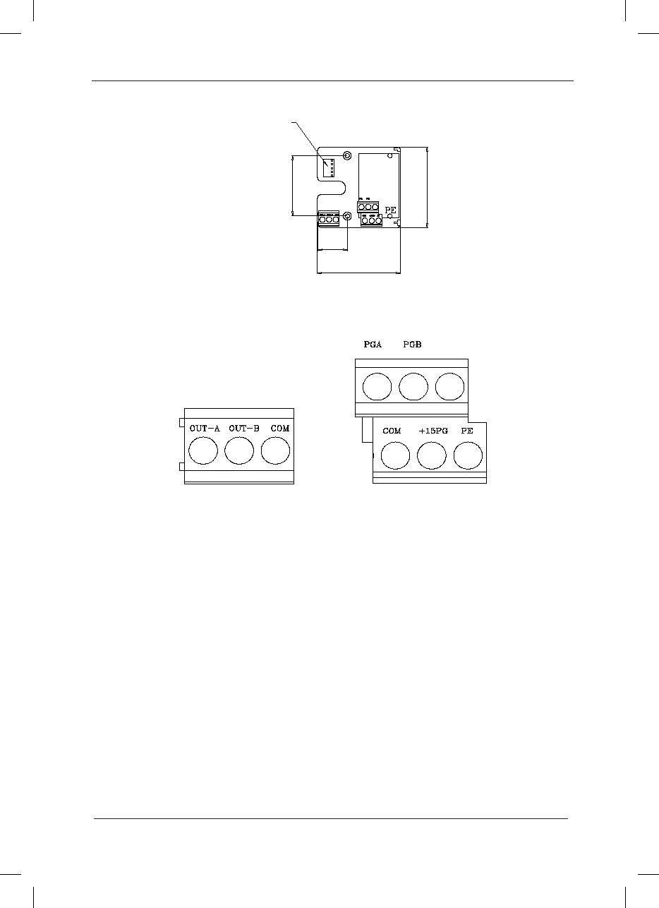
Appendix A: Fig.3 PG Card Terminal Denition
A.2 Instruction for use
A.2.1 Function
It must select PG card when the user has needs for speed sensor vector control. The standard
congurations of the PG card include processing circuits of two orthogonal encoder signals,
encoder signal able to receive open collector output or push-pull collector output, and encoder
power supply (xed at +15V output). In addition to the standard congurations, the enhanced
PG card can divide the input encoder signal and output processing circuits of two orthogonal
signals. Please select according to the actual needs.
A.2.2 Terminal and Toggle Description
The PG card has 9 user terminals. Refer to Section 1.3 for details. Among these terminals,
+15PG and COM are working power output of encoder, PGA and PGB are signal input terminal
of encoder, OUT-A, OUT-B and COM are frequency division signal output terminal, and PE is
shielded cable terminal (Since the PE is not earthed inside the PG card, the user can connect it
to the earth based on the actual needs).
In the PG card with frequency division, the frequency division coefcient is determined by the
toggle switch on the PG card. The toggle switch has 5 digits. The frequency division coefcient
 Loading...
