Type Terminal Symbol Terminal Name Function Description
Relay
Output
T/A-T/B
Normally closed
terminal
AC250V
,
3A
,
COSø=0.4
.
DC 30V
,
1A
Contact driving capacity:
AC250V, 3A, cosφ=0.4.
DC 30V, 1A
T/A-T/C
Normally open
terminal
Auxiliary Interface
J1
Functional
expansion card
interface
28-core terminal and interface with optional
cards (I/O expansion card, multiple pump
water supply expansion card, extension card,
MODBUS communication card and various bus
cards)
CN3
External
keyboard
interface
external keyboard and parameter copy unit
interface
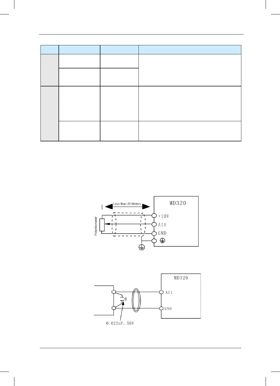
3) Description of Connection of control terminals:
A. Analog input terminal:
Since the weak analog voltage signal is easy to suffer external interferences, it needs to employ
shielded cable generally and the length shall be no longer than 20 meters, as shown in Fig. 3-9.
In case the analog signal is subject to severe interference, and analog signal source side shall
be installed with lter capacitor or ferrite magnetic core, as shown in Fig.3-10.
Fig.3-9 Schematic Diagram for Connection of Input Terminal of Analog Signal
 Loading...
