3.2.3 Connections
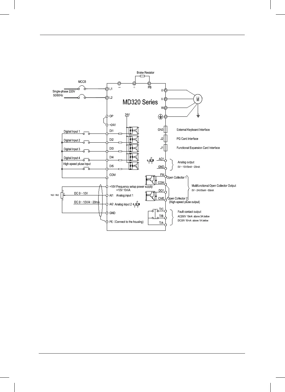
Schematic Diagram for Single-phase Inverter Connection:
Fig.3-5 Schematic Diagram for Single-phase Iinverter Connection
Precautions are as follows:
Terminal1.
◎
refers to Main circuit terminal
,
Terminal ○ refers to control circuit terminal.
There is 0.4kW~2.2kW Build-in brake unit optional.2.
B which is followed the product model represents Self-braking unit.3.
Braking resistor’s selection is based on the user demand. See the prototyping Guide of 4.
braking resistor for details.
Signal lines and power line must be separated alignments, if you want to control cables 5.
and power cable cross, let them cross by 90 degree angle. It is best to choose shielded
twisted-pair cabling for analogue signal, the selection of power cable is shield three-core
cable(The specication should enlarge a le as much as the ordinary electric cables),or
follow the inverter user manual.
 Loading...
