Chapter 4 Operation and Display
4.1 Introduction to Operation and Display Interface
With the operation panel, it can perform such operations on the inverter as function parameter
modication, inverter working status monitoring and inverter running control (startup and stop).
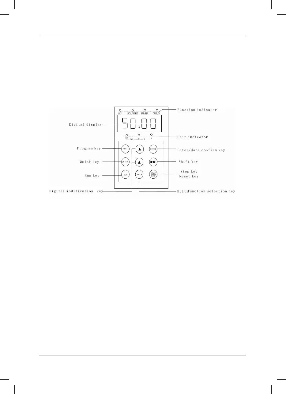
Refer to Fig.4-1 for the physical appearance and functional zone of the operation panel.
Fig.4-1 Operation Panel Diagram
Description of Function LED Indictor: 1)
RUN: When it is OFF, it indicates the inverter is in stop status; when it is ON, it indicates the
inverter is in rotation status.
LOCAL/REMOT: It is the LED indictor for keyboard operation, terminal operation and remote
operation (communication control). When it is OFF, it indicates the keyboard operation control
status; when it is ON, it indicates the terminal operation control status; when it flashes, it
indicates the remote operation control status.
FWD/REV: It is the LED indictor for forward/reverse rotation. When it is OFF, it indicates the
inverter is in forward rotation status; when it is ON, it indicates the inverter is in reverse rotation
status.
TUNE/TC: It is the LED indictor for tuning. When it is ON it indicates the torque control status;
when it is OFF, it indicates the speed control status.
Units of LED indictor description:2)
Hz refers to the unit of frequency
A refers to the unit of current
V refers to the unit of voltage.
 Loading...
