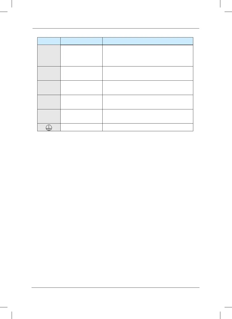
Terminals
Name Description
R
、
S
、
T
Input terminal of
three-phase power
supply
AC input single-phase power connection point
(+)
、
(-)
Negative and positive
terminals of DC bus
Shared DC bus input point (connection point of
external brake unit of more than 37kW)
(+)
、
PB
Connecting terminal
of brake resistor
Connection point of Brake resistor of less than
30kW
P
、
(+)
Connection terminal
of external reactor
Connection point of external reactor
U
、
V
、
W
Output terminal of
inverter
Connect the three-phase motor
Earth terminal Earth terminal
1
)
Precautions on Wiring:
A) Input power L1, L2 or R, S and T:
The cable connection at the input side of the inverter has no phase sequence requirement.
B) DC bus (+) and (-) terminals:
Note that the (+) and (-) terminals of DC bus have residual voltage right after power-on. It
needs to wait until the CHARGE indictor is OFF and make sure that the voltage is less than
36V prior to wiring connection. Otherwise there may be danger of electric shock.
When selecting external brake unit for the inverter of more than 37kW, the poles of (+) and (-)
shall not be connected reversely, or it may damage the inverter and even cause re.
The wiring length of the brake unit shall not exceed 10 meters. Twisted wires or pair wires shall
be used and connected in parallel.
Do not connect the brake resistor directly to the DC bus, or it may damage the inverter and
even cause re.
C) Connecting terminals (+) and PB of brake resistor:
The connecting terminals of the brake resistor are effective only for the inverter of less than
30kW with built-in brake unit.
The prototype of brake resistor can refer to the recommended value and the wiring length shall
be less than 5 meters. Otherwise it may damage the inverter.
D) Connecting terminals P and (+) of external reactor:
For the inverter of more than 75kW with external reactor, when assembling, remove the
connector between terminals P and (+) and connect a reactor instead.
E) Terminals U, V, W at the output side of the inverter:
 Loading...
