41
System components
Product Support: www.instron.com
Do not connect the two exhaust ports together.
In some situations, unexpected grip motion can result. To prevent this, do not link the
exhaust ports (for example with a “T” or “Y” fitting). The two exhaust ports must remain
separate.
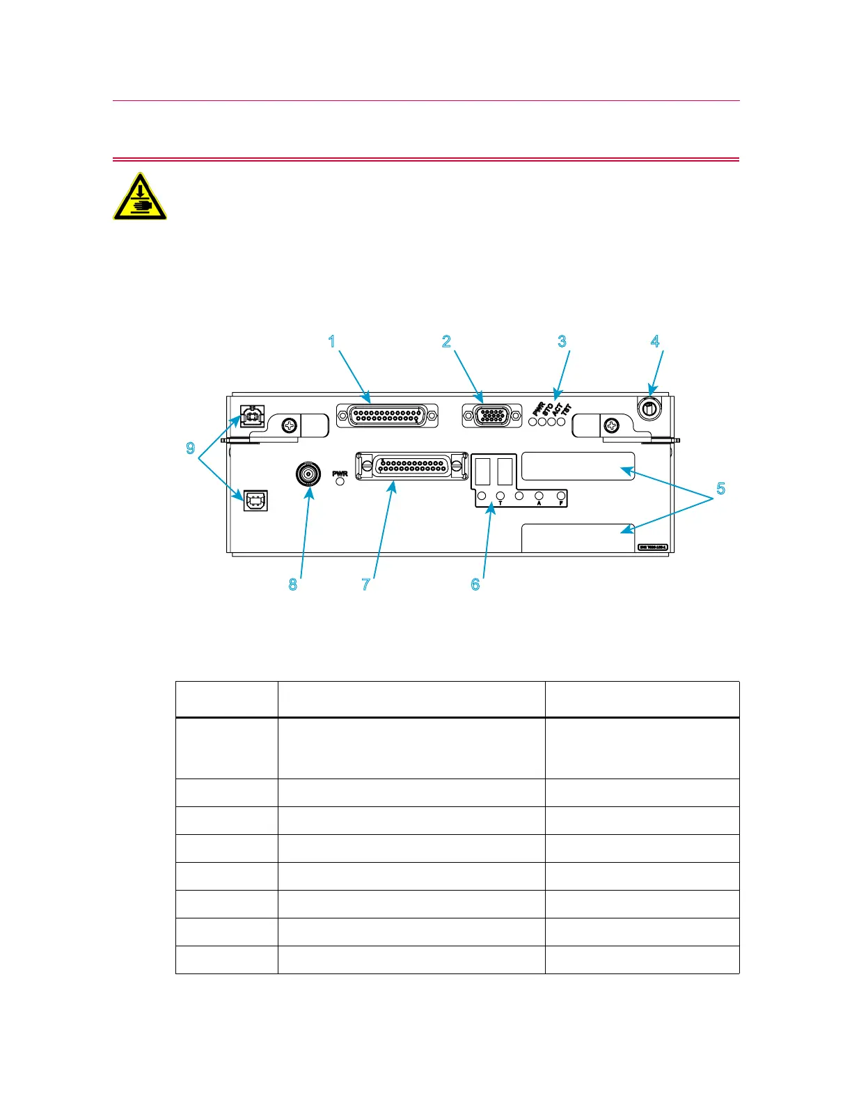
Controller connections detail
Figure 7. Controller connections detail
Legend for Figure 7
Label Component More detail
1 Encoder connector Connects to various
accessories, including AVE2
and AutoX extensometers
2 Foot switch connector
3Status indicators
4 PIP jack
5 Strain connectors Optional
6Status indicators
7 Force connector Connects to load cell
8 Sync connector