Intel® Server Board M10JNP2SB User Guide
23
5. Server Board I/O
5.1 PCIe Add-In Card Support
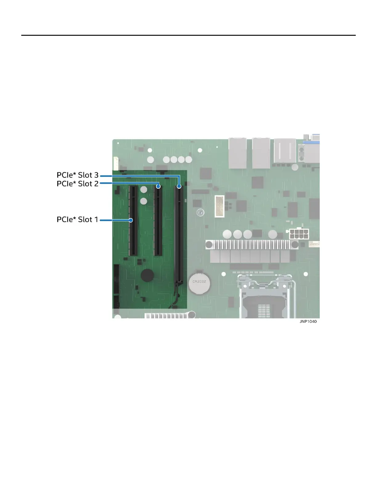
The server board provides three PCI Express* (PCIe*) slots labeled: “PCIe#1”, “PCIe#2”, and “PCIe#3”. The
PCIe* interface of the Intel® Server Board M10JNP2SB is fully compliant with the PCIe* Base Specification,
Revision 3.0 supporting the following PCIe* bit rates: 3.0 (8.0 GT/s), 2.0 (5.0 GT/s), and 1.0 (2.5 GT/s).
PCIe add-in card slots and their properties are as follows:
• Slot 1: PCIe* 3.0 x8 slot (x4 electrical)
• Slot 2: PCIe* 3.0 x8 slot (x8 electrical)
• Slot 3: PCIe* 3.0 x16 slot (x8 electrical)
Figure 10. PCIe slot identification
5.1.1 PCIe* Enumeration and Allocation
The BIOS assigns PCI bus numbers in a depth-first hierarchy, in accordance with the PCI Local Bus
Specification, Revision 3.0. The bus number is incremented when the BIOS encounters a PCI-PCI bridge
device.
Scanning continues on the secondary side of the bridge until all subordinate buses are assigned numbers.
PCI bus number assignments may vary from boot to boot with varying presence of PCI devices with PCI-PCI
bridges.
If a bridge device with a single bus behind it is inserted into a PCI bus, all subsequent PCI bus numbers below
the current bus are increased by one. The bus assignments occur once, early in the BIOS boot process, and
never change during the pre-boot phase.
The BIOS resource manager assigns the PIC-mode interrupt for the devices that are accessed by the legacy
code. The BIOS ensures that the PCI BAR registers and the command registers for all devices are correctly set