Intel® Server Board M10JNP2SB User Guide
24
up to match the behavior of the legacy BIOS after booting to a legacy OS. Legacy code cannot make any
assumption about the scan order of devices or the order in which resources are allocated to them. The BIOS
automatically assigns IRQs to devices in the system for legacy compatibility. A method is not provided to
manually configure the IRQs for devices.
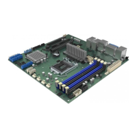
5.2 1U One-Slot PCIe Riser Card Option (iPC – JNP1URISER)
The server board provides support for one riser card with a single PCIe 3.0 slot. Due to the size of the riser
card (x16 mechanical) it can only be installed in PCIe* Slot #3 as shown in Figure 10.
Figure 11. 1U one-slot PCIe* riser card option (iPC – JNP1Uriser)
Table 6. One-slot PCIe* riser card slot description
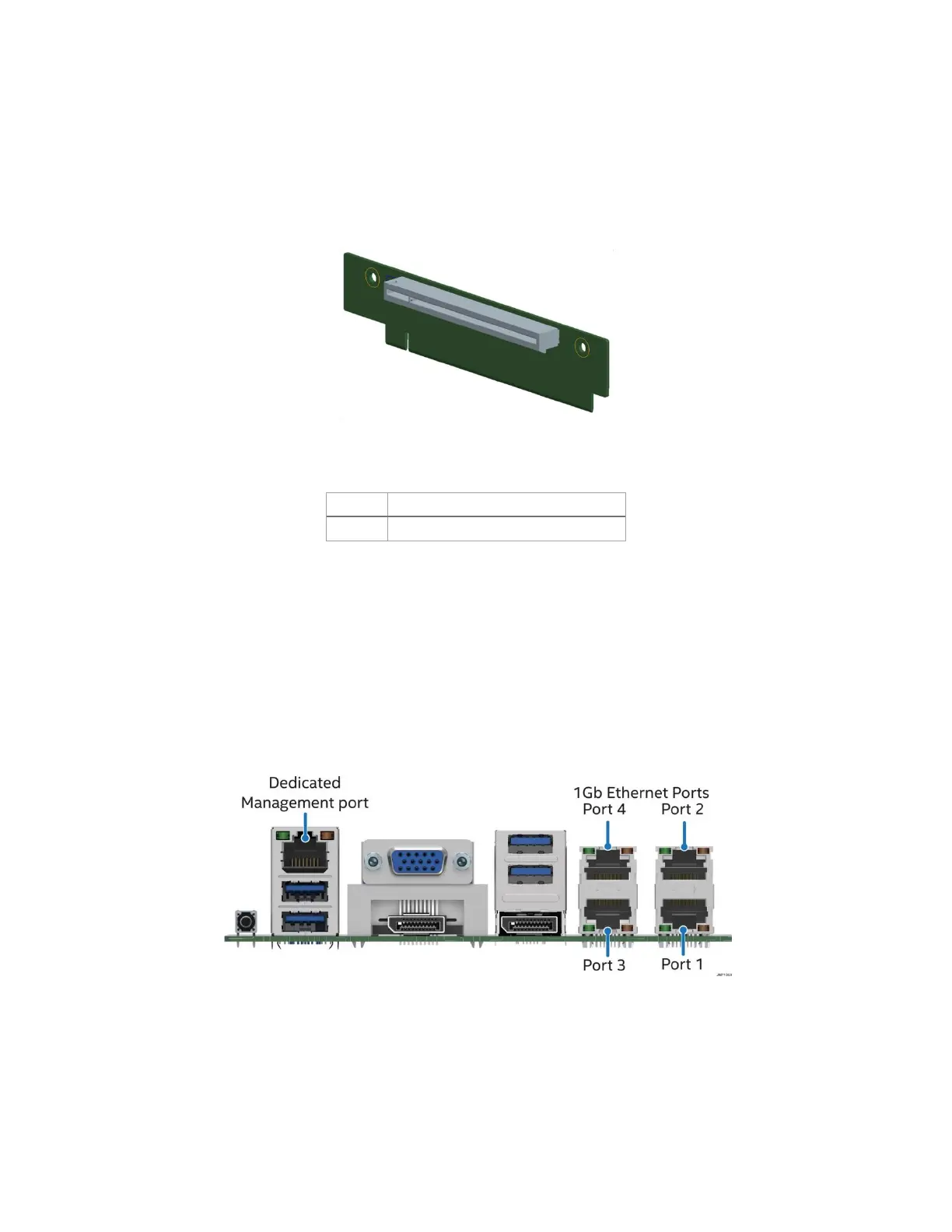
5.3 Networking
The Intel® Server Board M10JNP2SB includes five external RJ45 connectors providing support for the
following features:
• Four 1 Gb Network Interface Ethernet Ports
• One dedicated 1 Gb server management port
The following illustration shows the ports located on the back edge of the server board.
Figure 12. Rear networking ports
The five onboard Ethernet ports have green and yellow LEDs that indicate LAN status. Table 7 lists the
different LED states.