Intel® Server Board M10JNP2SB User Guide
33
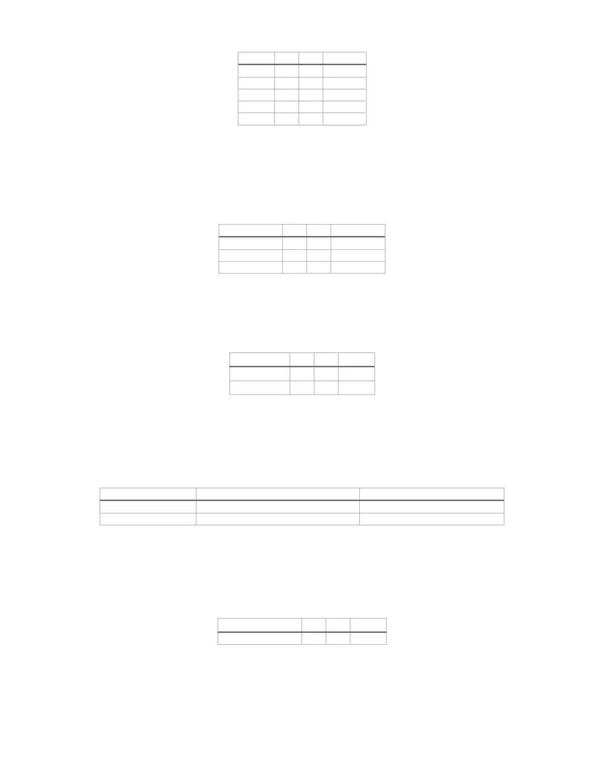
Table 21. COM2 port pin-out
7.6.2 Power Supply Monitoring Interface (PSMI) Connector
The server board includes a PSMI connector for the BMC to monitor and communicate with the installed
power supplies. The pin-out for this connector is shown in Table 22.
Table 22. PSMI connector pin-out
7.6.3 IPMB Header
The server board includes an IPMB SMBUS* header. Table 23 provides the pinout for the header.
Table 23. IPMB header pin-out
7.6.4 Chassis Intrusion Header
The server board includes a 2-pin chassis intrusion header which can be used when the chassis is configured
with a chassis intrusion switch. Table 24 provides the pin-out for the header.
Table 24. Chassis intrusion header pin-out
FM_INTRUDER_HDR_N is pulled HIGH
FM_INTRUDER_HDR_N is pulled LOW.
7.6.5 ID LED Header
The server board includes a 2-pin header to connect a chassis-mounted ID LED. Table 25 provides the
pinout for the header.
Table 25. ID LED header pin-out