Intel® Server Board M10JNP2SB User Guide
41
9.4 Processor Heat Sink Installation
The instructions in this section describe the process of installing a processor heat sink. The process
described is for reference purposes only. The selected heat sink to install on the server board may be
different.
Required Tools and Supplies
• Anti-static wrist strap and conductive foam pad (recommended)
• Phillips* head screwdriver
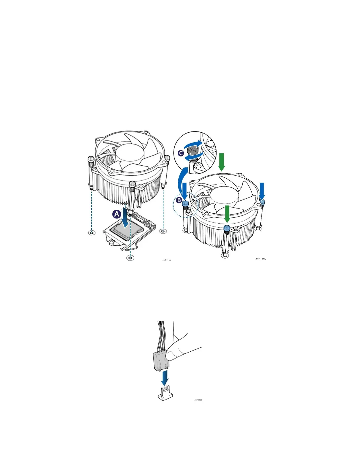
If present, remove the protective cover from the bottom of the heatsink to expose the thermal interface
material. Make sure the push pins on the heatsink are rotated clock-wise.
Figure 25. Installing the heat sink
1. Place the heat sink on top of the installed processor aligning the 4 plastic pins with the holes in the
server board (see letter A).
2. Push the pins through the holes on the server board doing two opposite corners at a time until they click
into place (see letter B).
3. Tighten the 4 screws on the push pin head using a Phillips head screwdriver.
Figure 26. Connecting the fan cable
4. Connect the fan cable to the 4-pin processor fan connector labeled “CPU_Fan” on the server board to
complete the installation.