5.3.1 MAC Address Definition
The Intel® Server Board M10JNP2SB has the following MAC addresses assigned at the factory:
• RJ45 Network Interface Ethernet Port 1 (base MAC address)
• RJ45 Network Interface Ethernet Port 2 (base MAC address + 1)
• RJ45 Network Interface Ethernet Port 3 (base MAC address + 2)
• RJ45 Network Interface Ethernet Port 4 (base MAC address + 3)
• Dedicated management port (base MAC address + 4)
• Shared management interface (through Ethernet port 4 – base MAC address +5)
5.4 USB
USB support is provided through onboard internal and external connectors as described in the following
sections.
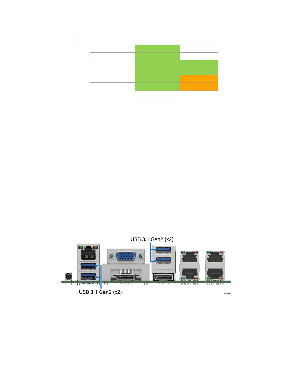
5.4.1 External USB 3.1 Connectors
The server board includes four (stacked 2x2) USB 3.1 Gen2 ports on the back edge of the server board. Two
ports are located below the Dedicated Management port, while the other two are located above one of the
display port connectors as shown in Figure 13.
Figure 13. External USB 3.1 Gen2 ports
5.4.2 Front Panel USB 3.1 Connector
A blue 20-pin (2x10) shrouded connector on the server board (labeled “USB3_FPIO1”) provides the option of
routing two USB 3.1 ports to the front of a given chassis. Figure 14 provides the location of the connector on
the server board. See Section 7.4.2 for detailed connector pinouts.