Intel® Server Board M10JNP2SB User Guide
39
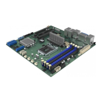
Figure 21. Opening the processor load plate
3. Lift open the processor load plate.
CAUTION: The pins inside the processor socket are extremely sensitive. Other than the processor, no object
should make contact with the pins inside the processor socket. A damaged processor socket pin will render
the socket inoperable, and will produce erroneous processor or other system errors if used.
NOTE: The underside of the processor has components that may damage the socket pins if installed
improperly. The processor must align correctly with the socket opening before installation. Do not drop the
processor into the socket!
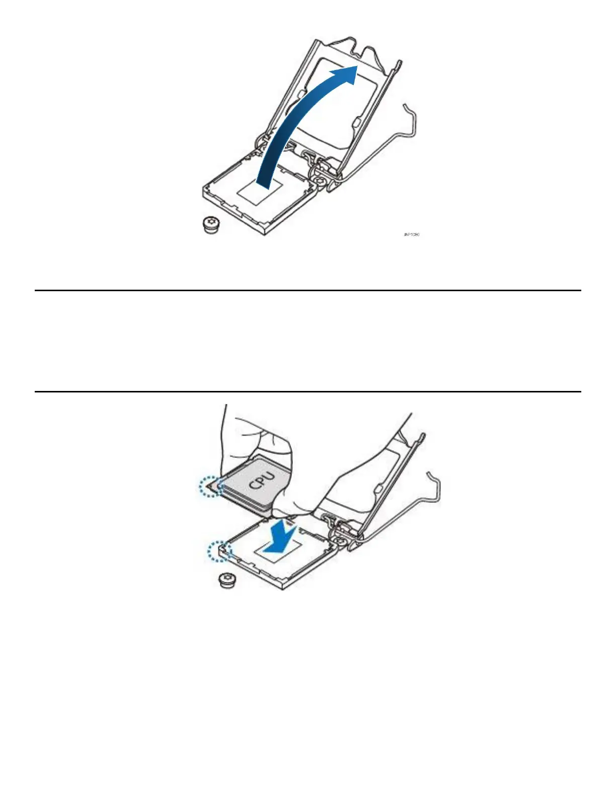
Figure 22. Installing the processor
4. Remove processor from its packaging. If present, carefully remove the protective cover from the bottom
side of the processor, taking care not to touch any processor contacts. Orient the processor with the
socket so that the gold key on it is aligned to the mark on the socket.