EasyManua.ls Logo

Intel M10JNP2SB - 7 On-Board Connector;Header Pin-Out Overview; Power Connectors; Table 8 PWR1 Pin-Out; Table 9. PWR2 Pin-Out

Intel M10JNP2SB
75 pages
Print Icon
To Next Page IconTo Next Page
To Previous Page IconTo Previous Page
Loading...
Intel® Server Board M10JNP2SB User Guide
29
7. On-Board Connector/Header Pin-Out Overview
This chapter identifies the pin-outs for on-board connectors and headers on the Intel® Server Board
M10JNP2SB that provide an interface for system options and features, onboard platform management, and
other user accessible options or features. For more details on the location of the connectors in this chapter,
see Figure 2.
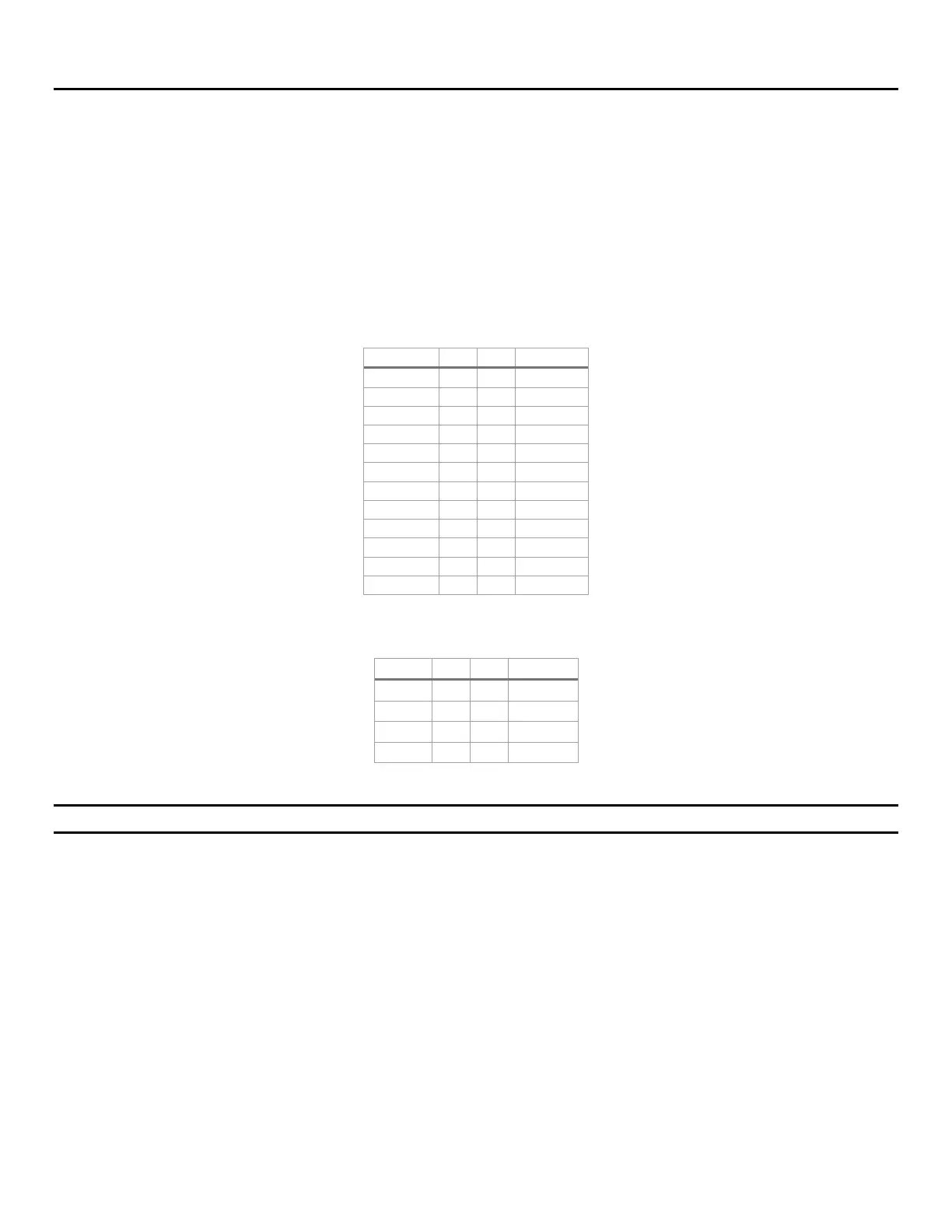
7.1 Power Connectors
The server board includes two power connectors labeled “PWR1” and “PWR2”. Table 8 and Table 9 provide
the pinout for these connectors.
Table 8 PWR1 pin-out
Signal
Pin
Pin
Signal
+3.3 Vdc
1
13
+3.3 Vdc
+3.3 Vdc
2
14
-12 Vdc
GND
3
15
GND
+5 Vdc
4
16
PS_ON#
GND
5
17
GND
+5V
6
18
GND
GND
7
19
GND
PWR_OK
8
20
NC
5 VSB
9
21
+5 Vdc
+12 Vdc
10
22
+5 Vdc
+12 Vdc
11
23
+5 Vdc
+3.3 Vdc
12
24
GND
Table 9. PWR2 pin-out
Signal
Pin
Pin
Signal
GND
1
5
+12 Vdc
GND
2
6
+12 Vdc
GND
3
7
+12 Vdc
GND
4
8
+12 Vdc
Important Note: PWR1 and PWR2 must be connected to power for the server board to boot correctly.

Table of Contents

Related product manuals