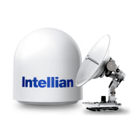
ACU Cable Connection
Name of ACU Rear Panel
The following gure shows the ACU's rear panel.
Antenna Control Unit (ACU)
NMEA 2000 &
NMEA 0183 (GYRO)
Input
Modem
Console
PC
Interface
Wi-Fi
Dongle
Antenna
Connector
Modem RS232/422
Interface
LAN 2 Port
LAN 1 Port
LAN 4 Port
LAN 3 Port
BUC
Interface
Modem/Primary
Rx/TX Connector
Secondary
Rx/TX Connector
Power Cord
Connecting to the Antenna
Connect the "RF Cable (not supplied by Intellian)" from the "ANTENNA" connector on the rear of the ACU to
the "RF Connector" inside cable entry of radome (Antenna).
Figure: ACU to Antenna Cable Connection
Figure: Name of ACU Rear Panel
Above Decks
Below Decks
ACU
Antenna
Antenna
TX, RX, 48V DC Power

 Loading...