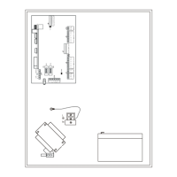
Refer to “NXG-8(E) Wiring Diagram” on
page 17. The NXG-4 unit functionality is the
same as NXG-8 except that the connections
are spatially orientated differently.
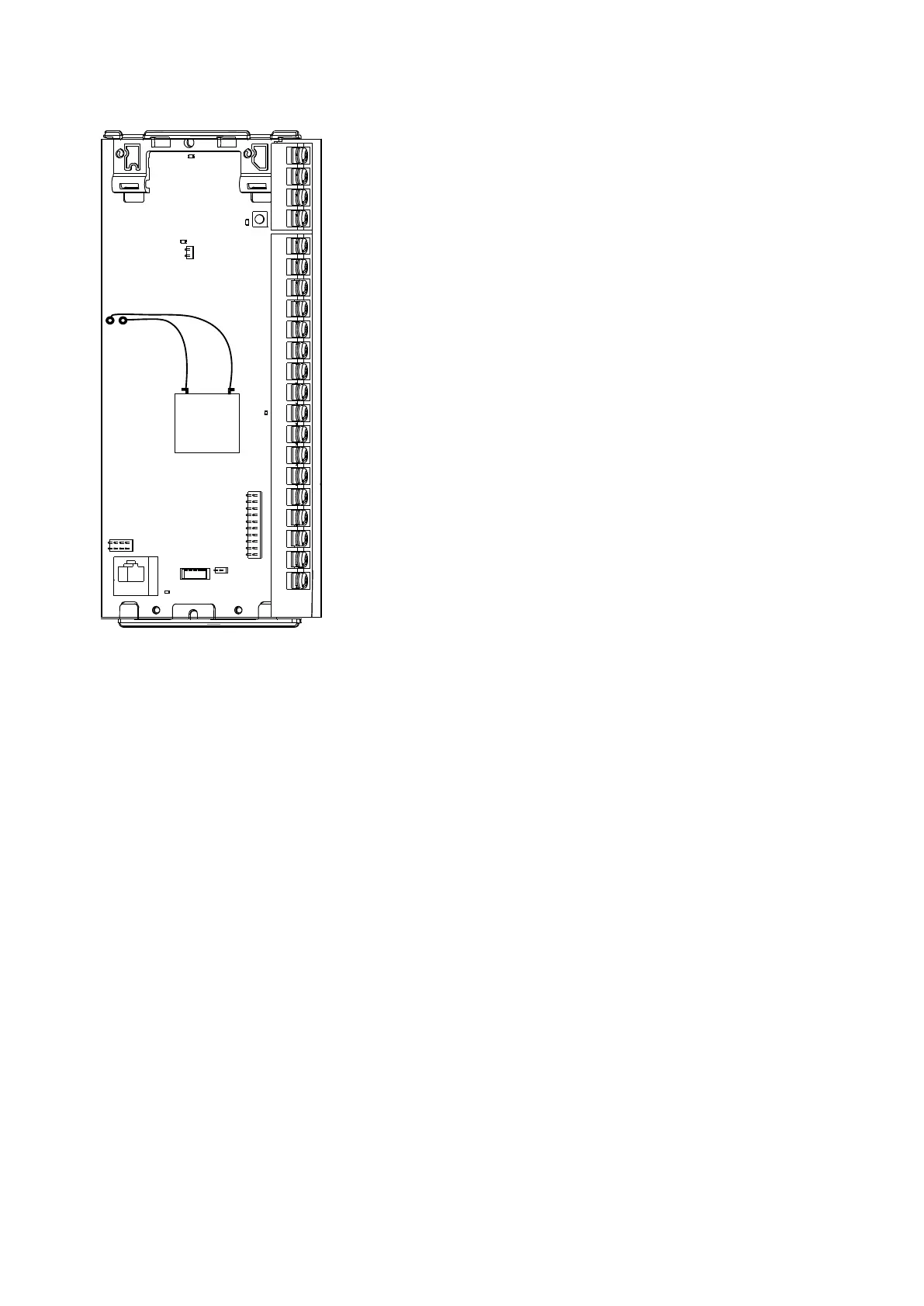
NXG-4 Terminals
Refer to “NXG-8(E) Terminals” on page 19.
The NXG-4 unit functionality is the same as NXG-8 except it provides two
additional connections:
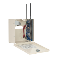
• Antenna 1: After the board is installed in the metal enclosure, insert the
antenna with the corresponding icon.
• Antenna 2: After the board is installed in the metal enclosure, insert the
antenna with the corresponding icon.
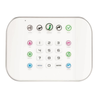
NXG-4 LEDs
Refer to “NXG-8(E) LEDs” on page 20.
The NXG-4 unit functionality is the same as NXG-8 except it has the following
additional LED:
• D5 RF: Red LED blinks when message is sent or received from a 63bit /
80plus transmitter.
 Loading...