EasyManua.ls Logo

Intermec EasyCoder PC4 - Media Dimensions and Formats

Intermec EasyCoder PC4
88 pages
Print Icon
To Next Page IconTo Next Page
To Previous Page IconTo Previous Page
Loading...
Intermec EasyCoder PC4—Service Manual 51
Chapter 7—Main Board
7.2 Accessing the Main Board
e main board is fitted with a single screw to the bottom of the base
frame (see Chapter 5.2). Remove the screw and disconnect the cables as
required. When the printer is assembled, the main board is supported by
mouldings extending both from the base frame and from the bottom cover.
Always disconnect the power supply and take precautions against elec
-
trostatic discharges before touching the main board.
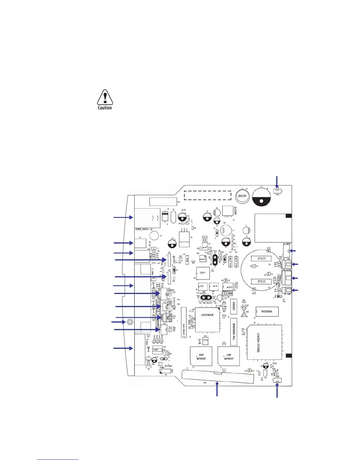
7.3 Connections
is simplified illustration shows where the various cables are connected to
the main board.
SW1 On/Off Switch
JP6 USB
CN2 Printhead
CN1 Printhead
JP3 Centronics
JP4 RS 232
Printhead GND
J1 Power Supply
JP10 Upper Label Gap Sensor
JP13 Lower Label Gap
Sensor/Black Mark Sensor
JP7 Ribbon End Sensor
JP9 Feed Switch/LED
JP15 Memory Cartridge
JP11 Headlift (left)
JP1 Motor
JP8 LT
S
JP14 Cutter
JP2 Thermistor
JP12 Headlift (right)
PRODUCT/REV. NO.

Other manuals for Intermec EasyCoder PC4

Related product manuals