Intermec EasyCoder PC4—Service Manual 21
Chapter 4 —Print Fram
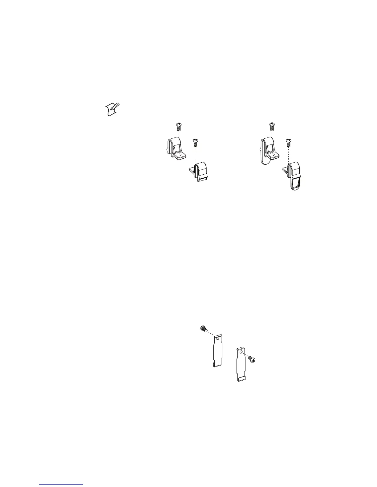
4.3 Top Cover Locks
Description
e top cover locks are shorter in the DT model than in the TTR model,
because there is normally no need to separate top cover and the print
frame, when there is no need for ribbon reload.
Note: Parts are marked with “L” or “R” indicating left or right side (frontal
view).
DT Model TTR Model
Replacement
e locks are attached to the print frame moulding with Phillips screws. To
access the left side lock, you will need to remove the cable cover as shown
in the instructions for replacing the Feed Switch PCB earlier in this chap
-
ter.
4.4 Base Lock Spring Hooks
Description
Two spring hooks that are engaged by the base lock (see Chapter 5.7) are
fitted to the print frame moulding using Phillips screws. e spring hooks
are identical for the DT and TTR models.
Replacement
e left-side spring hook is fitted inside the same housing as the Feed
switch PCB. To access it, you will need to remove the cable cover as shown
in the instructions for replacing the Feed Switch PCB earlier in this chap
-
ter.
e right-side spring hook is easily accessible in the DT model whereas in
the TTR model, you will need to dismantle the ribbon takeup mechanism
(see Chapter 4.8).