10 Intermec EasyCoder PC4—Service Manual
Chapter 2—Main Parts
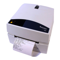
2.1 Taking the Printer Apart
e EasyCoder PC4 is a so called double clam-shell design, where the print
frame and the top cover are hinged to a base frame.
e bottom part of the base frame is enclosed by the bottom cover, which
is held by four Phillips screws. Once the bottom cover has been removed,
the two pairs of bolts and E-rings that hold the base frame, the print frame,
and the top cover become accessible. You will also need to disconnect a
number of cables from the main board.
In most cases, you do not need to dismantle the base frame, print frame,
and top cover.
In the illustration in Chapter 2.3, all cables have been omitted. Detailed
descriptions of the main parts and their sub-assemblies can be found in
Chapters 3 to 7.
All screws are Phillips-type of various sizes.
2.2 Reassembling the Printer
Reassemble the printer in reverse order. Refer to Chapter 7.3 for a connec-
tion diagram, which helps you put all the cables back correctly. When put
-
ting the printer back into the bottom cover, tilt it a little so the rear plate is
inserted first, then carefully manipulate the front part in place. Secure the
assembly with the four Phillips screws.