Intermec EasyCoder PC4—Service Manual 39
Chapter 5—Base Frame
5.5 Motor assy
Description
e motor assembly consists of a stepper motor and a thermistor mounted
on a bracket, which is attached to the inner, right side of the base frame
moulding. e motor pulley and two shafts protrude through holes in the
base frame moulding. Outside the moulding two gears are fitted on the
shafts. e gears form a train from the motor pulley to the gear of the platen
roller. e platen roller gear engages the ribbon takeup gear, when the print
frame is closed.
Note: e stepper motor differs between the 202.3 dpi (8 dots/mm) and
the 300 dpi (11.81 dots/mm) models.
e termistor protects the stepper motor from overheating by stopping the
printing at approx. +80°C (+176°F). is is indicated by the LED flashing
red. When the temperature gets down to approx. +60°C (+140°F), which
usually takes 4.5 to 5 minutes, the LED switches back to green and any
interrupted print job is automatically resumed. Overtemperature is caused
by excessive load on the stepper motor (high print speed, continuous print
-
ing of too many labels, etc.) possibly in combination with a high ambient
temperature.
e stepper motor is connected to JP1 and the thermistor to JP2 on the
main board.
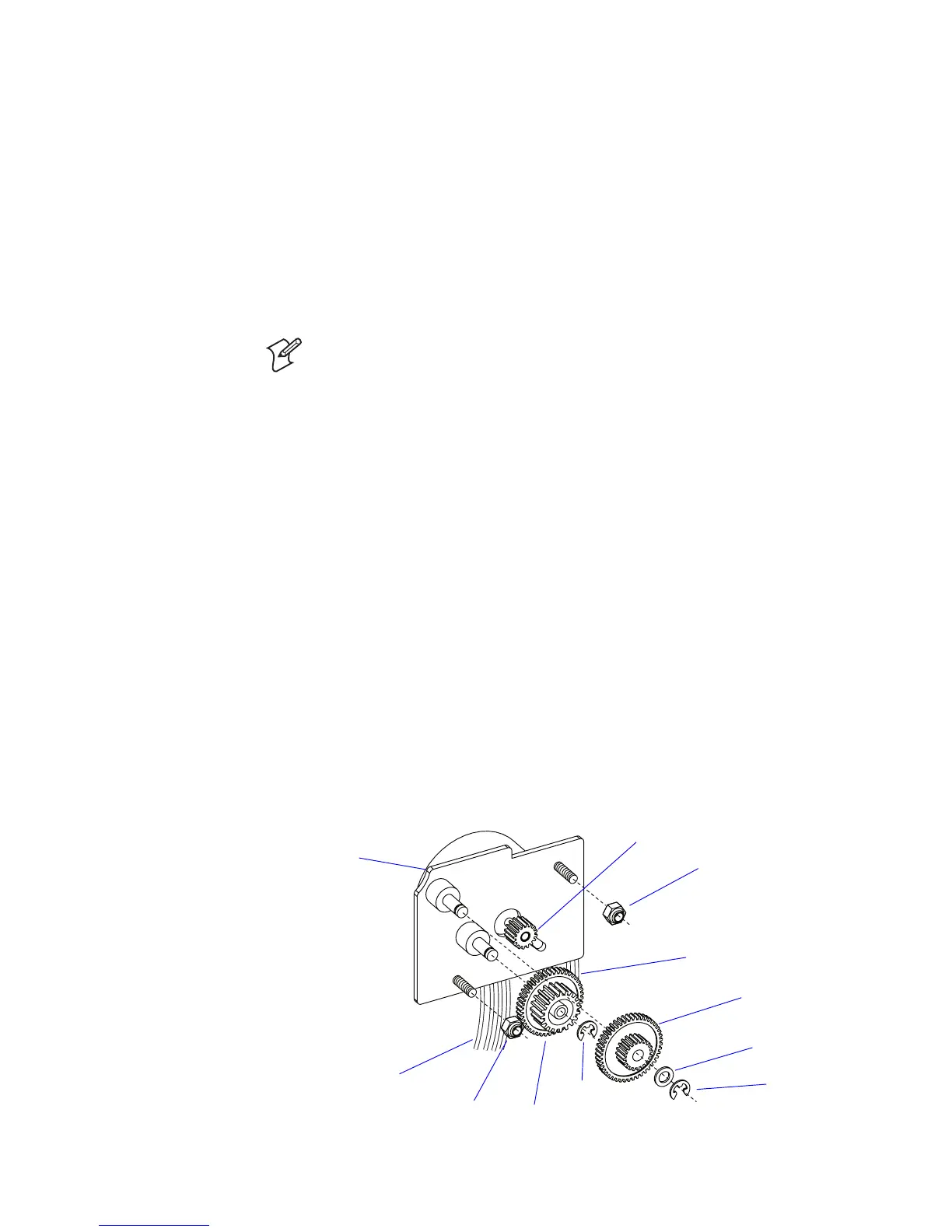
Replacement
e motor assy mechanism comes as a complete unit including stepper
motor, bracket, thermistor, gears, washer, E-rings, and nuts.
• Disconnect the cables from JP1 and JP2 on the main board.
• Remove the E-rings, washer, and gears
• Remove the two M3 self-locking nuts.
• Pull out the motor and bracket.
• Install a replacement unit in reverse order.
Washer
E-ring
E-ring
To JP1 on main board
To JP2 on main board
Motor, thermistor, and bracket
M3 nut
M3 nut
Pulley
Gear
Gear