64 Intermec EasyCoder PD4—Service Manual
Chapter 11—Switching Power Module
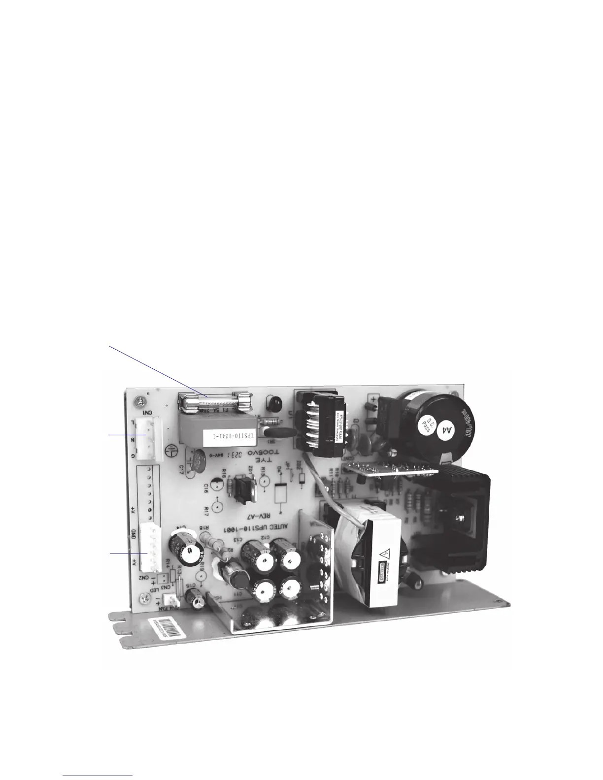
11.1 Switching Power Module
Description
The switching power module receives 90/260 VAC, 47 to 63 Hz from
the power switch kit via a cable harness connected to CN1 on the power
module. The power module converts the current using switching technique
and delivers +24 VDC ± 2% to the main board via a cable harness from
CN2 on the power module to CN28 on the main board.
Consumption
Stand-by: 0.15A
Normal operation: 4.5A
Peak: 10.5A
Switched power modules are generally diffi cult to repair. If one compo-
nent fails due to aging or overload, a number of other components will
also break as a consequence. They are hard to troubleshoot, because the
power module often is “dead” or the fuses blow immediately. It is also
impossible to guarantee the life of a repaired power module, because
components may still work but be on the verge of failing. Thus, if a fuse
blows, only replace it once. Do not attempt to repair the power module
or replace the fuse a second time, but replace the entire unit.
Fuse 5A
slow
CN1
90-260
VAC In
CN2
24 VDC
to main
board