I
O
B
u
s
I
n
p
u
t
C
o
n
s
o
l
e
I
O
P
o
r
t
s
C
P
U
Flash (1)
Me
m
or
y
(1
M
)
Flash (2)
Memor
y
(1
M
)
EDO
RAM
(2M)
RT
C
Flash
Mem
ory
E
xtension
(
2M)
Pow
e
r
s
u
p
pl
y
24 VDC
Po
w
er
Inp
u
t
F
E
E
D
P
AUSE
CANCEL
S
ystem Buss
Sens
o
rs
Ribbon End
TPH open
TPH temp
termistor
Power detection
Power Temp
Sensor
BM sensor
GAP sensor
Virtu
a
lpot
RS-2
3
2por
t
IEEE 1284
USB
LC
D
B
u
zz
e
r
LEDs
Stepper Motor
Printhead
Cutter
Rewinder unit
D
ri
vers
EEPROM
Sensors
A
/D
l
ine
68 Intermec EasyCoder PD4—Service Manual
Chapter 12—Main Board
12.1 Description
Models
There are three different main boards for the EasyCoder PD4 depending
on printer model:
• EasyCoder PD4 No display 203.2 dpi
• EasyCoder PD4 LCD display 203.2 dpi
• EasyCoder PD4 LCD display 300 dpi
The printer must be fi tted with the correct type of main board or it will
not work.
All types of main board are based on the same circuit board but the com-
plement of circuits differ. They are all designed to work with ESim v5.xx
for EasyCoder PD4 or later versions.
The main boards are delivered as complete units. Do not attempt to repair
or modify a main board.
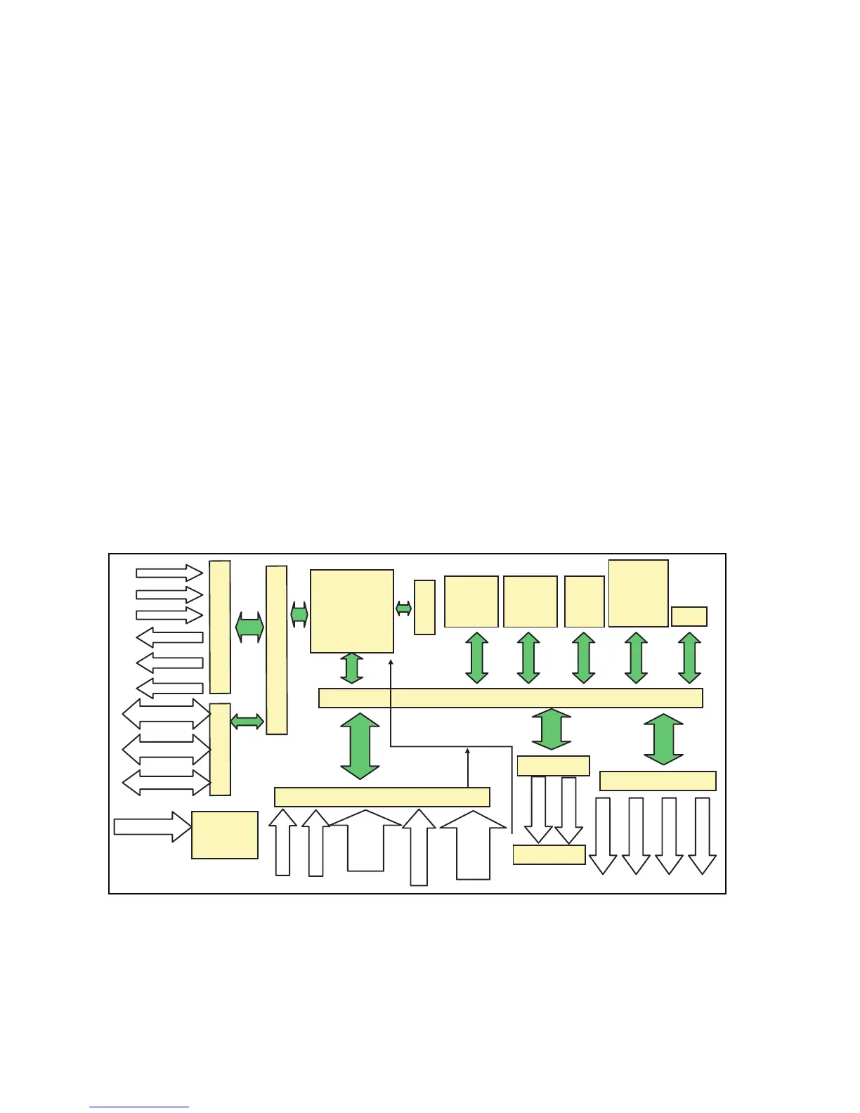
The main board has a 16 bit microprocessor and, as standard, a memory of
2MB fl ash and 2MB DRAM.
The models with an LCD display has a real-time clock and the memory
can be expanded using a 2MB fl ash memory module.
Block Diagram