168 Intermec EasyCoder PF2i, PF4i, and PF4i Compact Industrial—Service Manual
Chapter 14—Interfaces
14.5 Installing an Optional Interface Board
To install an optional interface board, proceed as follows (the illustrations
show a Serial/Industrial Interface board.)
Note: This chapter does not apply to installation of any type of EasyLAN
interface board, which instead is described in Chapter 14.9.
• Open the electronics compartment, see Chapter 11.2.
Switch off the power and disconnect the power cord. The electronics
compartment contains high voltage components and wires. Do not open
the electronics compartment before the printer is safely disconnected
from any AC supply.
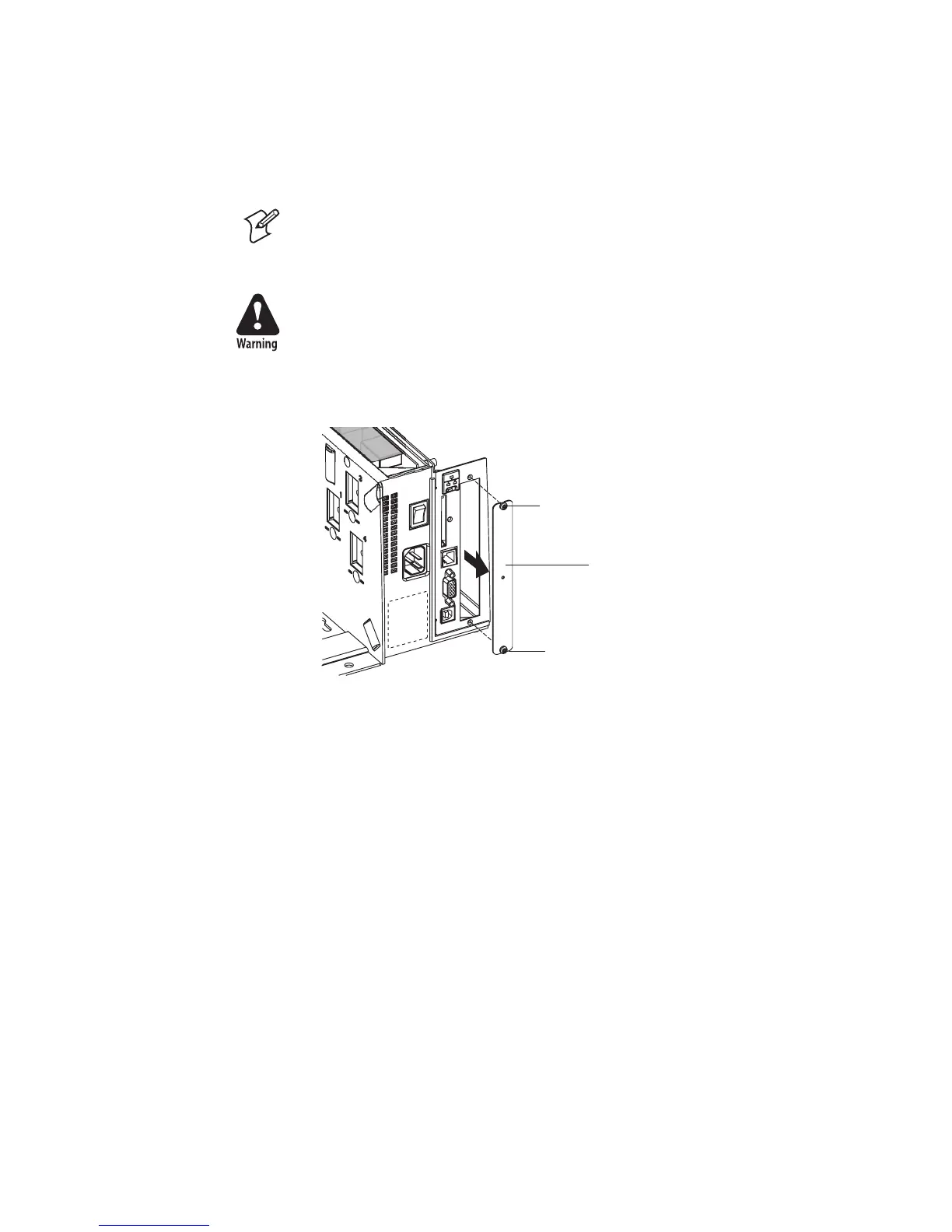
• Remove the two #T10 Torx screws that hold the interface cover plate.
Remove the cover plate.
• Save the cover plate for possible later use. Keep the screws.
• Remove the #T20 Torx screw fi tted on the hexagonal spacer at the
center of the CPU board. Keep the screw.
• If necessary, fi t or remove circuits and straps on the interface board
according to the descriptions of each board later in this chapter.
• Attach the fl at cable included in the kit to connector J62 (marked “EXP
BOARD”) on the CPU board (see illustration on the next page).
• Insert the interface board with the component side facing right, as seen
from behind.
#T10 Torx screw
Cover plate
#T10 Torx screw