LIST OF FIGURES
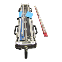
Belt Splicing System v.2.0
LOF
SAFETY
Figure A: Heat Wand and Temperature
Control Box hazards ...........................................3
Figure B: Belt cutting and trimming hazards ........3
Figure C: Clamping Fixture hazards.....................4
TABLE OF CONTENTS
LIST OF FIGURES
1 EQUIPMENT OVERVIEW
Figure 1A: Splicing System............................ 1- 1
2 SPLICING SYSTEM COMPONENTS
Figure 2A: System accessories
(generic photo) ............................................. 2- 1
Figure 2B: Storage case ................................ 2- 1
Figure 2C: Clamping Fixture........................... 2- 2
Figure 2D: Top Clamp/Cut Guide set.............. 2- 3
Figure 2E: Heat Wand components................ 2- 4
STANDARD PROCEDURES
3 SET UP THE SPLICING SYSTEM
Figure 3A: Clamping Fixture on horizontal
conveyor ...................................................... 3- 2
Figure 3B: Add clamps ahead of
Clamping Fixture on an inclined conveyor ...... 3- 2
Figure 3C: Attach Crank Handle ..................... 3- 2
Figure 3D: Latch Heat Wand in Stand............. 3- 3
Figure 3E: Check voltage requirements .......... 3- 3
Figure 3F: Check voltage requirements........... 3- 4
Figure 3G: Turn Power on.............................. 3- 4
Figure 3H: Check Control Box display ............ 3- 4
4 PREPARE BELT ENDS
Figure 4A: Clean belt ends ............................. 4- 2
Figure 4B: Pull the belt across BOTH decks,
and align the drive bars with grooves............. 4- 2
Figure 4C: Belt drive bar
engagement/alignment .................................. 4- 3
Figure 4D: Place Cut Guide on belt................. 4- 3
Figure 4E: Tighten Cut Guide in place............. 4- 3
Figure 4F: Check setup before cutting ............ 4- 3
Figure 4G: Hold the utility knife against
the Cut Guide Edge........................................ 4- 4
Figure 4H: Inspect cut belt ends..................... 4- 4
Figure 4I: Inspect cut..................................... 4- 4
5 ALIGN AND SECURE BELT ENDS
Figure 5A: Align belt ends on Grooved Deck... 5- 2
Figure 5B: Belt ends extending....................... 5- 2
Figure 5C: Lower Cut Guide on Grooved Deck 5- 2
Figure 5D: Position and tighten thumb knobs . 5- 2
LIST OF FIGURES