EasyManua.ls Logo

INVT DA180-S2R8SG0

INVT DA180-S2R8SG0
316 pages
To Next Page IconTo Next Page
To Previous Page IconTo Previous Page
Loading...
DA180 series basic AC servo drive Function codes
-133-
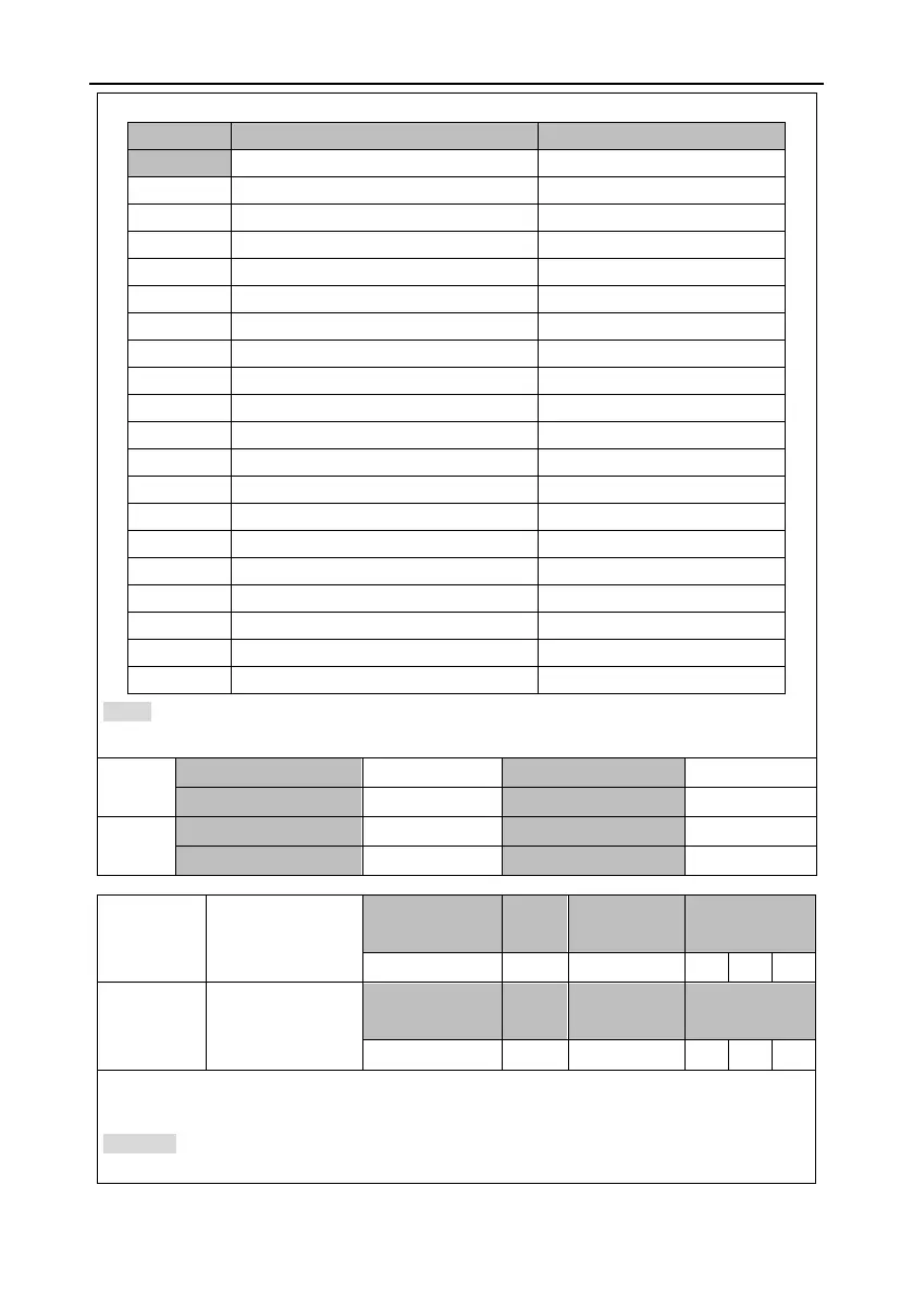
This group of parameter specifies monitoring parameters for analog output.
Setting
Meaning
Unit
[0]
Invalid
-
1
Motor speed
r/min
2
Speed in a position command
r/min
3
Internal position command
pulse (encoder unit)
4
Speed command
r/min
5
Torque command
0.1%
6
Torque feedback
0.1%
7
Command position deviation
reference unit
8
Encoder position deviation
pulse (encoder unit)
9
Fully-closed loop position deviation
pulse (grating ruler unit)
10
Hybrid control deviation
reference unit
11
Main circuit DC voltage
V
12
Forward torque limit
0.1%
13
Reverse torque limit
0.1%
14
Speed limit
r/min
15
Inertia ratio
%
16
Analog input 1*
V
17
Analog input 2*
V
18
Analog input 3*
V
19
Drive temperature
°C
Note: * If P3.31 and P3.33 are set to 1000, analog input 1, analog input 2, and analog input 3
automatically output the voltage that is input from analog input terminals.
P3.30
1
Data size
16bit
Data format
DEC
Modbus address
1660, 1661
CANopen address
0x231E, 0x00
P3.32
1
Data size
16bit
Data format
DEC
Modbus address
1664, 1665
CANopen address
0x2320, 0x00
P3.31
Voltage gain of AO
1
Setting range
Defaul
t
Unit
Applicable
mode
1214748364
1
[P3.30 unit]/V
P
S
T
P3.33
Voltage gain of AO
2
Setting range
Defaul
t
Unit
Applicable
mode
1214748364
1
[P3.32 unit]/V
P
S
T
This group of parameter specifies the gain of analog output. The gain units are associated with
P3.30 and P3.32.
Example: Assume that the actual speed is output from the terminal AO1, 10V corresponds to the
speed of 3000 r/min and 0V corresponds to 0. Then P3.30 must be 1 and P3.31must be 300. See

Table of Contents

Related product manuals