Goodrive35 Series Closed-loop Vector Control VFD Function parameters
100
Detailed instruction of parameters
PID adjustment is different from the current running
direction, operate the close-loop adjustment output
that is opposite to current running direction..
LED hundreds: P00.08 is 0
0: Limit to the maximum frequency
1: Limit to frequency A
PID command of
ACC/DEC time
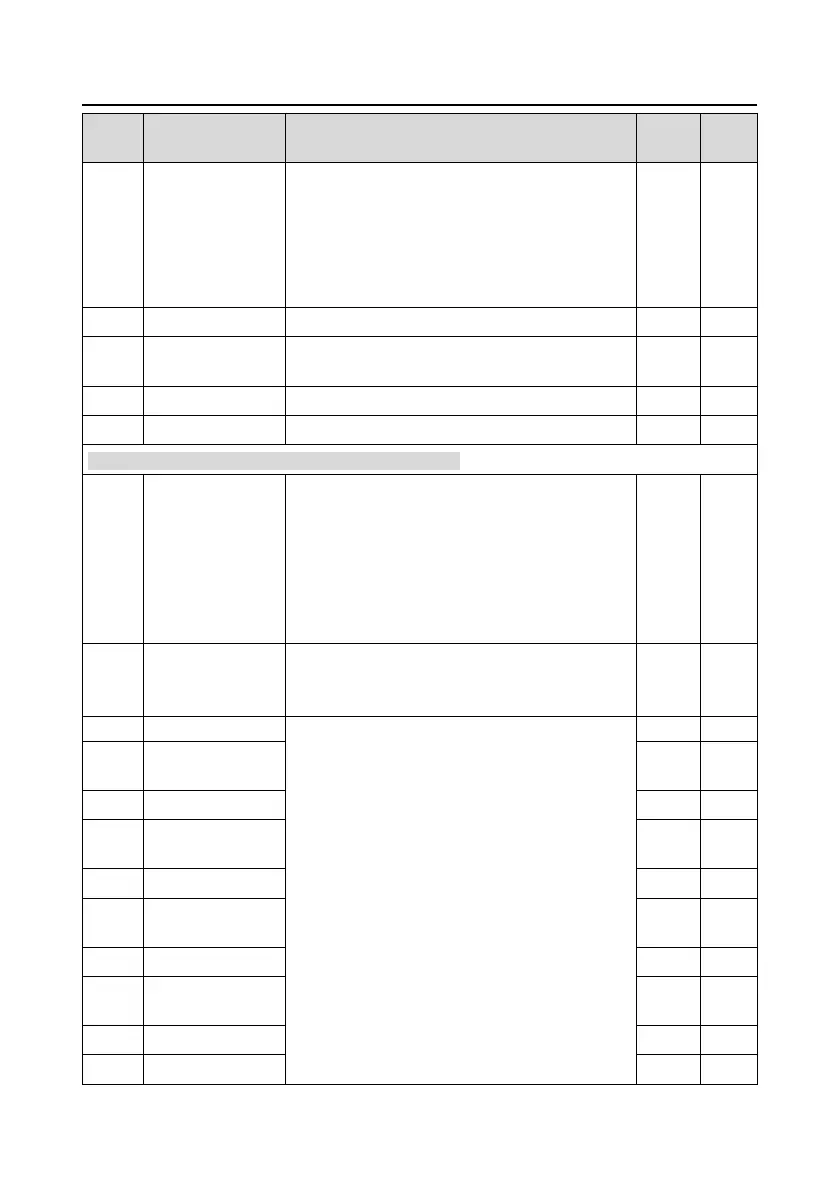
P10 Group Simple PLC and multi-step speed control
0: Stop after running once. The VFD has to be
commanded again after finishing a cycle.
1: Run at the final value after running once. After
finish a signal, the VFD will keep the running
frequency and direction of the last run.
2: Cycle running. The VFD keeps running until
receiving a stop command, then system will stop.
0: Power loss without memory
1: Power loss with memory; PLC record the running
stage and frequency when power loss.
The frequency setting range of stage 0–15:
-100.0–100.0%, 100.0% of the frequency setting
corresponds to max. output frequency P00.03.
The operation time setting of stage 0–15: the time
unit is determined by P10.37..
When selecting simple PLC running, set
P10.02–P10.33 to define the running frequency and
time of all stages.
Note: The symbol of multi-step determines the
running direction of simple PLC. The negative value
means reverse rotation.
The running time of
step 1
The running time of
step 2
The running time of
step 3
 Loading...
