Goodrive35 Series Closed-loop Vector Control VFD Function parameters
119
Detailed instruction of parameters
Evaluated motor
frequency
Evaluate the motor rotor frequency on closed-loop
vector
Range: 0.00–P00.03
Display current DC bus voltage of the VFD
Range: 0.0–2000.0 V
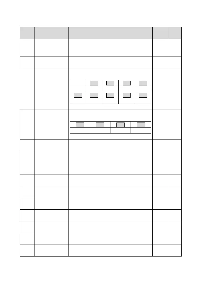
Digital input
terminals state
Display present digital input terminals state of the
VFD
Digital output
terminals state
Display present digital output terminals state of the
VFD
Display the adjustment via the VFD keypad
Range : 0.00 Hz–P00.03
Display the torque given, the percentage to the
current rated torque of the motor.
Setting range: -300.0%–300.0% (rated current of the
motor)
Display A1 adjustment voltage.
0.00–10.00 V
Display A2 adjustment voltage.
0.00–10.00 V
Display A3 adjustment voltage.
0.00–10.00 V
Display analog AI1 input signal
Range: 0.00–10.00 V
Display analog AI2 input signal
Range: 0.00–10.00 V
Display analog AI3 input signal
Range: -10.00–10.00 V
Display HDI input frequency
Range: 0.00–50.00 kHz
 Loading...
