Goodrive35 Series Closed-loop Vector Control VFD Basic operation instruction
171
External fault reset. It has the same function with the reset
function of STOP/RST on the keypad. This function can
realize remote fault reset.
The VFD decelerates to stop. But all running parameters
are in the memory state. For example, PLC parameters,
traverse parameters and PID parameters. After the signal
disappears, the VFD will come back to the state before
stopping.
When the external fault signal is sent to the VFD, the VFD
will report the fault and stop.
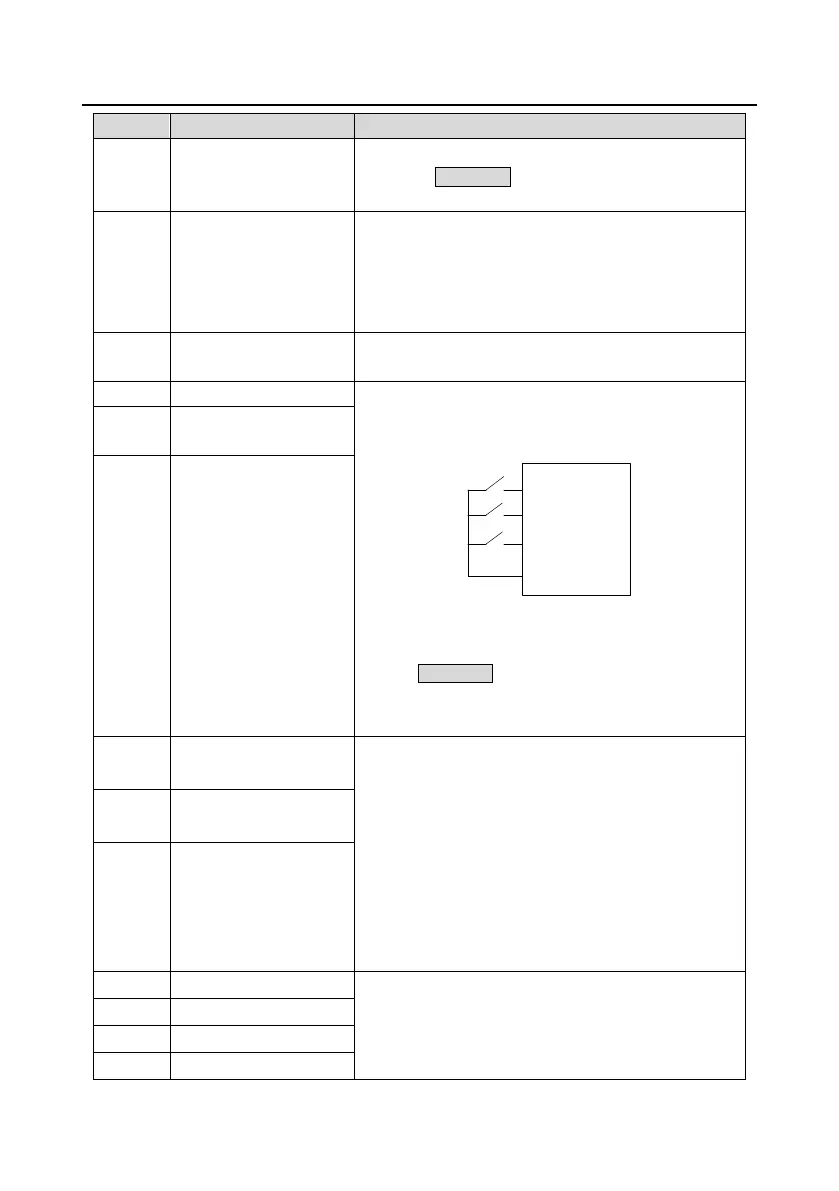
Frequency setting up (UP)
This parameter is used to modify the increasing and
decreasing command during the external terminal given
frequency.
K1
K2
K3
UP terminal
DOWN terminal
UP/DOWM
clear terminal
COM
Frequency increasing/decreasing setting clear terminal
can cancel the assistant channel frequency set by the
internal UP/DOWN of the VFD to make the given
frequency restore to the frequency given by the main
given frequency channel.
Frequency setting down
(DOWN)
Frequency
increasing/decreasing
setting clear
Switch between A setting
and B setting
This function can realize the shifting between the
frequency setting channels.
The 13
th
function can realize the shifting between A
frequency given channel and B frequency given channel.
The 14
th
function can realize the shifting between A
frequency given channel and the combination setting
channel set by P00.09. The 15
th
function can realize the
shifting between B frequency given channel and the
combination setting channel set by P00.09.
Switch between A setting
and combination setting
Switch between B setting
and combination setting
Multi-step speed terminal 1
The 16 stage speeds can be set by the combination of
digital state of four terminals.
Note: Multi-step speed 1 is the LSB; multi-step speed 4 is
the MSB.
Multi-step speed terminal 2
Multi-step speed terminal 3
Multi-step speed terminal 4

 Loading...