Digital Network Public Address & Voice Alarm System
8. Support monitoring output.
9. Support 24V phantom power supply.
10. Zone Paging priority is configurable.
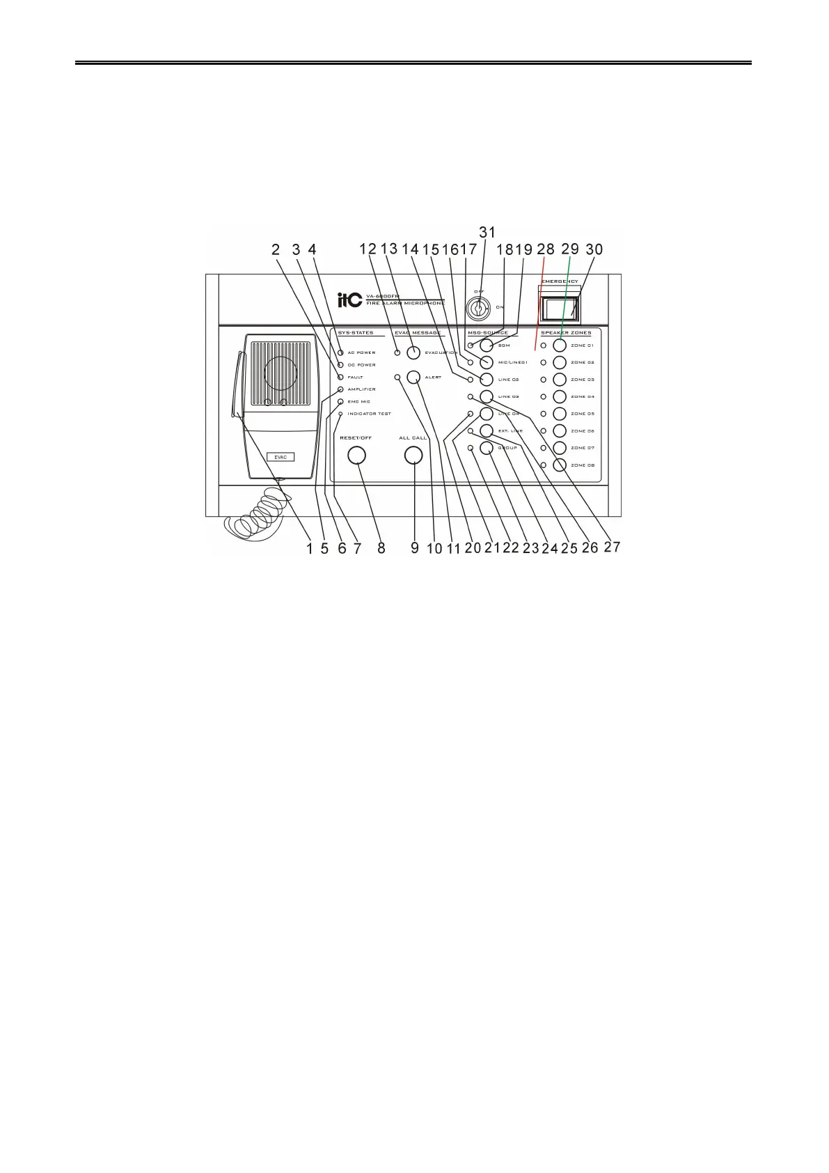
1. Handheld PTT(push to talk) MIC.
2. System status indicator(remind: not current MIC status indicator).
OFF—All device or module or spare power of the system is normal.
Yellow—All devices or module or spare power of the system is failure(all, part or one of them).
3. System all devices’spare DC power status indicator( if DC power has not be configured, system will
ignore its working status, default as normal).
OFF—System all devices’ spare DC work well.
Yellow—All devices or part of spare device’s spare power supply of the system is failure.
4. All system device main power status indication.
OFF—All device or module main power supply work well.
Yellow—All device or module main power supply is failure( all or one of them)
5. System amplifier working status indication.
OFF—All amplifier in system(including spare amplifier) work well.
Yellow—There is failure of all amplifier or one of them in this system(including spare amplifier)
6. Handheld PTT (push to talk) MIC working status indication.
Green flashing—Present zone paging MIC is switched by the audio with higher priority.
7. Panel indicator testing button: press all button in rear panel and indicator from green-red-yellow-turn to
normal.