Digital Network Public Address & Voice Alarm System
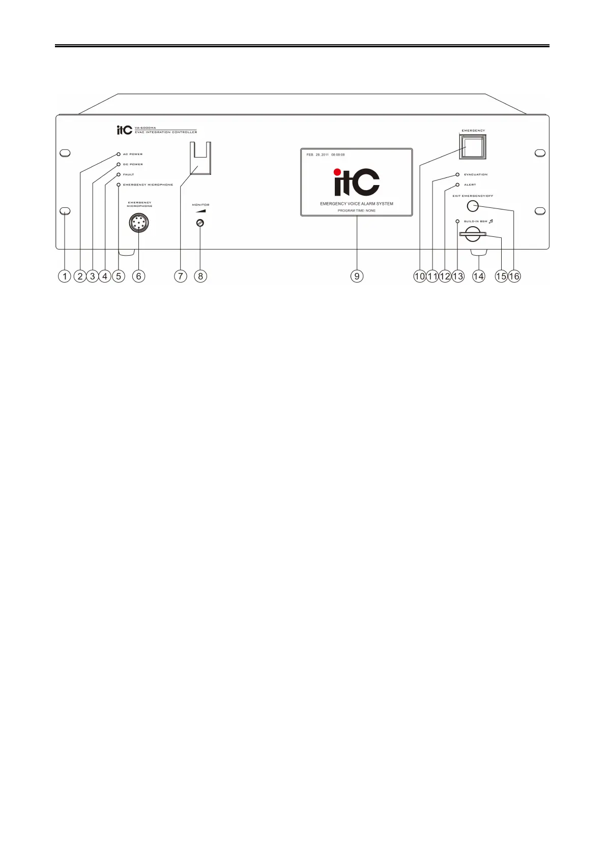
1. Installing hole(19” Cabinet).
2. Host main power indicator:
Green - indicates the current host AC power supply is normal.
Yellow - indicates the current host AC power is failure.
3. Host DC24V standby power indicator:
Green - indicates the current host standby power supply is normal.
Off - indicates the current host standby power supply is not configured.
Yellow - indicates the current host standby power is failure.
4. System Status Indicator:
Yellow - indicates the current system has faulty, lasting light indicates the user excutes a manual reset,
time lasting about 1 minute, if detects the system faulty has not ruled out, it will continue flash; when
system faulty rule out, indicator will automatically turn off.
Off - indicates the current system modules operate properly or the system does not open the module
testing.
5&6&7. Panel emergency PTT (push to talk) MIC.
“5” Color status explaination:
Off - PTT work normally.
Green - PTT being broadcast.
Yellow - Open circuit fault / PTT microphone internal short circuit fault.
“6”Aerial socket,can connect PTT MIC:
“7”PTT MIC hook.
Before pressing PTT switch, the host will make the following judgment, the performed functions as below
for reference:
If user selects partition, then it is zone selection broadcast.
If user does not select partition, then it is all zone broadcast.
 Loading...