Section C - Electrics
Service Procedures
Starter Motor
C-23 C-23
9803/9390-2
Starter Motor
TC-005
Starting Circuit Test
Before carrying out the voltmeter tests, check the battery
condition and ensure that all connections are clean and
tight.
To prevent the engine starting during the tests ensure that
the engine stop fuse is removed, (refer to Fuse
Identification page).
Check the readings in the following sequence using a
voltmeter. Unless otherwise stated, the readings must be
taken with the starter switch held in the 'start' position ('HS')
and the transmission forward/reverse selector in neutral.
Note: Do not operate the starter motor for more than 20
seconds at one time. Let the starter motor cool for at least
two minutes between starts.
1 Connect the voltmeter across the battery terminals.
K
Fig 8. ( T C-23). Reading in 'start' position: 10.0V
approximately. Minimum permissible reading in 'start'
position 9.5V.
A low reading probably indicates a fault in the starter
motor.
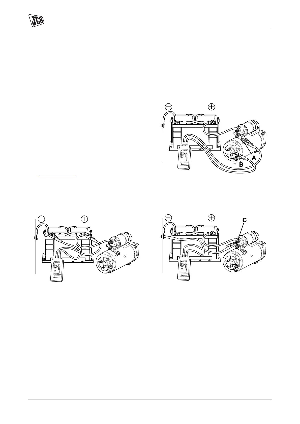
Fig 8.
2 Connect the voltmeter between the starter main
terminal 9-A and the commutator end bracket 9-B. In
the 'start' position, the reading should not be more
than 0.5V below the reading obtained in Step 1.
Minimum permissible reading in 'start' position 9.0V.
If the reading is within this limit, continue to Step 3. If
the reading is outside the limit, proceed to Step 4 and
Step 5.
Fig 9.
3 Connect the voltmeter between the solenoid terminal
10-C and a good earth. Minimum permissible reading
in 'start' position: 8.0V.
Fig 10.
a If the reading is less than specified, connect the
voltmeter between the neutral start relay terminal
11-D and earth. An increase in reading to 8.0V
indicates a fault in the wiring from the start relay to
the solenoid.