Section F - Transmission
Axles
Removal and Replacement
F-15 F-15
9803/9390-2
Removal and Replacement
Removal
Note: Ensure the axle hubs are clearly marked before
removal. K
General ( T F-13)
1 Drive the machine onto a dry, firm and level area.
2 Ensure the park brake is on.
3 The load bay needs to be raised to gain access to the
engine bay. Ensure that the load bay is properly
supported while working beneath it - refer to the
Handbook.
4 Disconnect the battery to prevent the engine being
started.
5 Raise and safely support the machine so that the
wheels can be safely removed.
6 Remove the wheels.
7 Ease the chain tension with adjusting bolts 2-F after
loosening bolts 2-E and the rear axles.
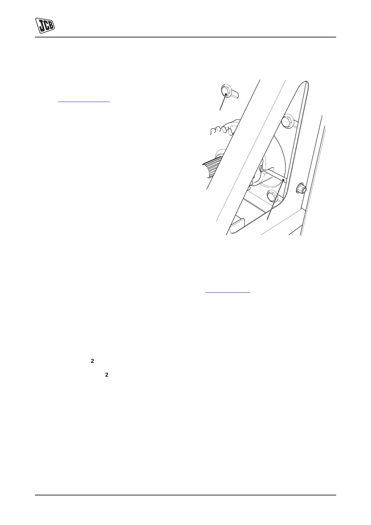
8 To remove an axle, first remove bolts 3-Y (4-off). The
front axles must be kept horizontal until the hub
splines are clear of the couplings 5-G and 5-H.
Fitting
1 The load bay needs to be raised to gain access to the
engine bay. Ensure that the load bay is properly
supported while working beneath it - refer to the
Handbook.
2 If fitting more than one axle, identify each axle for its
place in the chassis.
3 Where relevant, fit the rear axles first. The slot in the
hub must face towards the rear of the vehicle. Do not
fully tighten bolts 2-E (4 off).
4 Fit the tensioning bolts 2-F. Do Not fully tighten.
Fig 2.
5 Fit the splined couplings 4-G and 5-H to the drive
axles (or the transaxle output shafts).
6 Offer up the front drive axles to the chassis,
K
Fig 3. ( T F-16). Fit the bolts (4 off - one at each
corner) at 3-Y and torque tighten to 74 Nm (55 lbf ft).
C007560
F
E


 To Next Page