Section H - Steering
Rack and Pinion Steering Gear
Removal and Replacement
H-8 H-8
9803/9390-2
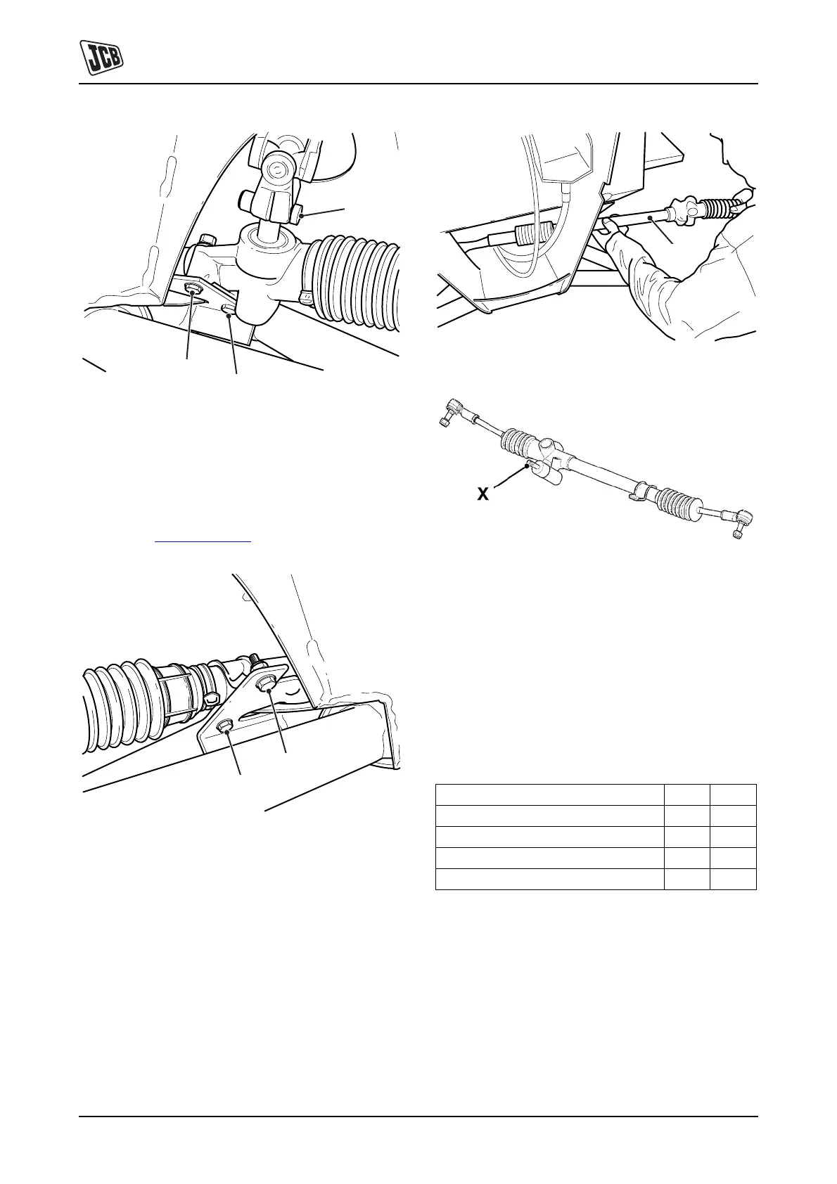
Fig 2. Steer Rack Mounting (Left Side) and Universal
Joint Connection
Steering Rack Mountings
On the left hand side, the steering rack connects to the
chassis through the steer rack body 2-B. On the right hand
side, it is secured to the chassis by a U-shaped mounting
bracket at C, K
Fig 3. ( T H-8)
Fig 3. Steer Rack Mounting (Right Side)
5 Remove the fasteners from both mountings.
Separate the pinion shaft 5-X from the universal joint
and withdraw the steering rack assembly 4-D from
the vehicle.
Fig 4.
Fig 5.
Replacement
Note: Replacement is the reverse of removal, but note the
following:
1 Renew all self-locking nuts.
2 When installing the steering rack and column, tighten
the UJ bolts last.
3 Correctly torque tighten fasteners:
Table 1. Torque Settings
4 Check steering alignment.
A
B
B
C
C
Item Nm lbf ft
Track rod ends to kingpins (7/16” nut) 25 - 30 19 - 22
Track rod end locknut 55 -60 41 - 44
Steer rack to chassis TBA
Universal joints TBA
D